Electrical Test & Measurement · Electrical Safety Testers

Multi-Channel Programmable Hipot Tester

Programmable hipot and insulation tester with 5 kV AC and 6 kV DC outputs, 50 GΩ insulation range, arc detection and four or eight scanning channels.

LK7140P (6 models) ·

Key specifications

AC output
0.10 to 5.00 kV, 0 to 20.00 mA
DC output
0.10 to 6.00 kV, 0 to 10.00 mA
Insulation resistance
0.1 MΩ to 50.0 GΩ at 0.10 to 1.00 kV
Current accuracy
±(2% of reading + 5 counts) on both AC and DC
Scanning channels
Four on LK7142-S4, eight on LK7142-S8, with the original output terminal kept as a common terminal
Arc detection
Nine levels, factory default level five, mapped to currents from 2.8 mA to 20 mA
Timing
Rise and fall 0.1 to 999.9 s; test 0.2 to 999.9 s; insulation wait 0.2 to 999.9 s
Display
Colour LCD with a guided menu, showing the measured value and the sorting result together
Storage
Ten programs on LK7142 and LK7162; one hundred on LK7140P and LK7142P; nine on the scanning models
Interfaces
HANDLER, RS232, USB device and USB host; PLC connector on the rear panel

A multi-terminal component is slow to test one point at a time, and the slowness is where mistakes come from. The scanning models in this range route the test voltage to four or eight terminals in turn, so a transformer or a multi-pin assembly is checked at every point from a single program.

Product overview

Six models share the same measuring engine and differ in body size, current range, program memory and channel count. The two compact models are 230 mm wide; LK7142 and LK7162 are 425 mm wide with ten programs; the two scanning models are 340 mm wide with four or eight channels and 18 kg.

All six cover 0.10 to 5.00 kV alternating and 0.10 to 6.00 kV direct, measure insulation resistance from 0.1 MΩ upwards, and run their timing from 0.1 s to 999.9 s in steps. The front panel is a colour screen with a keypad, and the rear carries HANDLER, RS232 and PLC connectors plus a USB host port.

How the multi-channel hipot tester works

The instrument ramps the output to the programmed voltage over a set rise time, holds it for the test time, and compares the resulting current with an upper and a lower limit. Above the upper limit the item is recorded as HIGH FAIL, which means the insulation broke down. Below the lower limit it is recorded as LOW FAIL, which usually means the item is not connected; the material notes that the lower limit has to be switched off for a component whose leakage is genuinely below the floor.

Insulation resistance is a separate measurement at 0.10 to 1.00 kV. The reading is taken after a waiting time that the operator sets, because a capacitive item draws a charging current that would otherwise be read as leakage.

On the scanning models a switch network connects the high-voltage source to one channel at a time, and the screen shows which channels are selected. The original output terminal stays connected as a common terminal, so the same instrument can still run a single-point test.

Arc detection watches for a fast current step that a normal current measurement would average out. The nine levels are mapped to currents from 20 mA at level one down to 2.8 mA at level nine, with level five as the factory setting.

How to select the right multi-channel hipot tester

Start with the number of test points. A single-point test on a completed appliance is served by LK7140P, LK7142P, LK7162 or LK7142. A transformer with several windings, or a connector with several pins, is where the S models earn their place, and the choice between four and eight channels follows the terminal count rather than the price.

The second question is current. The 20 mA models cover most components; LK7162 is quoted at 12 mA AC and 5 mA DC on its own card, which suits smaller components but limits the capacitance it can drive at full voltage.

The third is program memory. Ten programs suit a bench that runs a few products, one hundred suits a line with frequent changeover, and the scanning models hold nine.

The fourth is how the fixture talks to the instrument. All six offer HANDLER, RS232 and USB, and the rear PLC connector is available for a controller, so the interface decision is about the fixture rather than about the instrument.

Measurement limitations and selection considerations

The current reading includes the charging current of the item and its leads. At 5 kV a lead of a metre has enough capacitance to make a small component read higher than its true leakage, so the limit has to be set with the fixture in place.

The insulation measurement is only as good as its waiting time. Set too short, it reads the charging current; set too long, it slows the line without improving the result. The right value depends on the capacitance of the item, and the material gives the range but not a rule for choosing within it.

Scanning adds lead length and stray capacitance at every channel. The readings from different channels are therefore not directly comparable unless the leads are of equal length and routed the same way, which is a fixture design question rather than an instrument one.

Finally, arc detection is a diagnostic. It reports that a flashover occurred, not where in the item it occurred, and a component that trips the detector needs to be examined rather than simply retested at a lower sensitivity.

Features

  • Four or eight scanning channels on the S models, so a multi-terminal component can be tested at every point from one program without re-plugging leads
  • The original output terminal stays active as a common terminal in scanning mode, which means a single-terminal test still works on the same instrument
  • Voltage is ramped over a programmable rise time and brought down over a programmable fall time, so the stress profile is repeatable rather than dependent on the operator
  • Upper and lower current limits are both programmable, and the display distinguishes a high failure from a low one, which separates a breakdown from a missing connection
  • Insulation resistance is read after a settable waiting time, so the charging current of a capacitive sample has decayed before the value is taken
  • Fast discharge at the end of a direct or insulation test, so the item is not left charged when the leads are removed
  • Nine arc levels, with the level-to-current mapping given, so the sensitivity can be matched to the noise of the fixture
  • Storage for ten, one hundred or nine programs depending on the model, and a USB host port for exporting results and updating firmware

Technical specifications

Every value below is taken from source documentation. Where a parameter is not stated in the available material it is marked as information required rather than estimated.
Withstand output
AC voltage range0.10 to 5.00 kV on every modelStandard
DC voltage range0.10 to 6.00 kV on every modelStandard
AC current range0 to 20.00 mA, ±(2% of reading + 5 counts); 0 to 12.00 mA on the LK7162 model cardInformation required
DC current range0 to 10.00 mA, ±(2% of reading + 5 counts); 0 to 5.00 mA on the LK7162 model cardInformation required
Current limitsUpper and lower limits programmable; above the upper limit reads HIGH FAIL, below the lower limit reads LOW FAILStandard
Lower limit noteThe lower limit has to be switched off for a component whose leakage is below the settable floorStandard
Fast dischargeAutomatic discharge at the end of a direct testStandard
Arc detectionNine levels, default five; level one is 20 mA, level nine is 2.8 mAStandard
Insulation resistance
Test voltage0.10 to 1.00 kV, ±2%Standard
Range0.1 MΩ to 50.0 GΩ on the parameter table; 0.1 MΩ to 10.0 GΩ in the product summaryInformation required
Accuracy at 500 V or above1 MΩ to 1 GΩ, ±5% ±10 counts; 1 to 10 GΩ, ±10% ±10 counts; 10 to 50 GΩ, ±15% ±10 countsStandard
Accuracy below 500 V0.1 MΩ to 1 GΩ, ±10% ±10 countsStandard
Waiting time0.2 to 999.9 s, settable, before the reading is takenStandard
Discharge after testAutomatic at the end of the insulation measurementStandard
Timing and storage
Voltage rise time0.1 to 999.9 sStandard
Test time0.2 to 999.9 s on AC and DCStandard
Voltage fall time0.1 to 999.9 sStandard
Time accuracy±(1% + 0.1 s)Standard
Program memoryTen groups on LK7142 and LK7162; one hundred on LK7140P and LK7142P; nine on LK7142-S4 and LK7142-S8; the summary describes 99 stepsInformation required
Construction
DisplayColour LCD with a guided menu; the summary gives 240 × 64 resolution, the panel description gives a 4.3 inch colour screenInformation required
Front panel, scanning modelsPower switch, start and stop keys, screen, menu keys, numeric keypad, lock key, high-voltage output, low output terminal and the scanning terminalsStandard
Rear panelHANDLER connector, fan, PLC connector, mains inlet and RS232C connectorStandard
Dimensions, LK7142 and LK7162425 × 115 × 305 mm, 12 kgStandard
Dimensions, LK7140P and LK7142P230 × 90 × 370 mm, 12 kgStandard
Dimensions, LK7142-S4 and LK7142-S8340 × 120 × 450 mm, 18 kgStandard
Mains inputNot stated in the materialInformation required
Operating environmentNot stated in the materialInformation required

Available models

Selection table
Model Configuration Key ranges Availability
LK7140P Compact body, 100 program memory 0.10 to 5.00 kV AC, 0.10 to 6.00 kV DC; 0.1 MΩ to 50 GΩ The smallest body in the range
LK7142P Compact body, 100 program memory 0.10 to 5.00 kV AC, 0.10 to 6.00 kV DC; 0.1 MΩ to 50 GΩ Compact body with the larger program memory
LK7162 Wide body, 10 program memory, 12 mA AC and 5 mA DC 0.10 to 5.00 kV AC, 0.10 to 6.00 kV DC; 0.1 MΩ to 50 GΩ The model with the reduced current range
LK7142 Wide body, 10 program memory, 20 mA AC and 10 mA DC 0.10 to 5.00 kV AC, 0.10 to 6.00 kV DC; 0.1 MΩ to 50 GΩ The single-channel model with the full current range
LK7142-S4 Four scanning channels, 18 kg body 0.10 to 5.00 kV AC, 0.10 to 6.00 kV DC; 0.1 MΩ to 50 GΩ; 4 channels For a four-point component or fixture
LK7142-S8 Eight scanning channels, 18 kg body 0.10 to 5.00 kV AC, 0.10 to 6.00 kV DC; 0.1 MΩ to 50 GΩ; 8 channels The model shown in the supplied photograph

Customization

  • Test programs written for a particular component and its terminal order
  • Scanning leads and fixtures for the channel count in use
  • Rack mounting for a system cabinet

Certification and compliance

Certification documents not yet supplied

Certifications are only published once a certificate copy can be produced, so this section is deliberately empty rather than populated with assumed approvals. Tell us which approvals your application requires and we will confirm what is available for this instrument.

Parameters still to be confirmed

The following are required for a complete specification but are not stated in the documentation supplied to us. They are listed rather than estimated:

  • The AC and DC current ranges of LK7162, given as 0 to 12.00 mA and 0 to 5.00 mA on its model card and as 0 to 20.00 mA and 0 to 10.00 mA in the shared parameter table
  • The insulation resistance range, given as 0.1 MΩ to 50.0 GΩ in the parameter table and 0.1 MΩ to 10.0 GΩ in the product summary
  • The display, described as a 240 × 64 large LCD in the summary and as a 4.3 inch colour LCD in the panel description
  • The program memory, given as 99 steps in the summary, 10 groups on LK7142 and LK7162, 100 groups on LK7140P and LK7142P, and 9 groups on the scanning models
  • The arc detection mapping for direct current, which is listed only as nine levels without the current equivalents given for alternating current
  • The mains input voltage and frequency, which the material does not state
  • The operating temperature and humidity range, which the material does not state
  • The accessories supplied, since the material gives no packing list
  • Calibration certificate availability and the standard it would be issued against
  • Warranty period and its terms
  • Duty cycle for repeated tests at 20 mA
  • Ingress protection rating, which the material does not state

Frequently asked questions

What does the scanning option add over the single-channel model?

A switching network inside the instrument. On LK7142-S4 and LK7142-S8 the test voltage can be routed to four or eight terminals in turn, so a transformer with several windings or a component with several test points is checked at every point from one program. The original output terminal remains available as a common terminal, so a single-point test is still possible.

Why is there a settable waiting time for insulation resistance?

Because the insulation has to charge before its resistance can be read. A capacitive sample draws a falling current for a period after the voltage is applied, and a reading taken too early reports the charging current rather than the insulation. The waiting time lets the operator match the measurement to the sample rather than to a fixed delay.

What has to be confirmed before a quotation?

The number of test points, which decides between the single-channel and the scanning models; the current the sample draws, which decides between the 12 mA and 20 mA versions; the insulation resistance the standard requires, since the upper end of the range is quoted two ways; and whether the fixture is driven over HANDLER, RS232 or PLC.

Related products

Other models in the same range

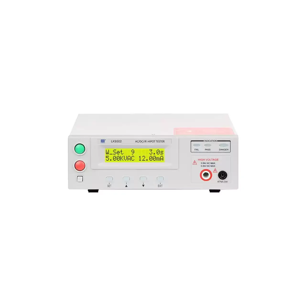
Light grey benchtop tester seen from the front, with a green start button and a red stop button stacked at the left, a yellow-green two-line LCD in the centre showing a set voltage and current, four soft keys beneath it, three indicator lamps at the upper right and a high-voltage terminal with a return terminal below it

LK7110+ (5 models) · Electrical Safety Testers

SCPI Programmable Hipot and Insulation Tester

Menu-driven programmable hipot tester with 5 kV AC and 6 kV DC outputs, insulation resistance to 9999 MΩ, four test modes and standard RS232 and PLC interfaces.

Output voltage
0 to 5 kV AC on all models; 0 to 6 kV DC on LK7122+, LK7122U and LK9302
Leakage ranges
0 to 12 mA AC and 0 to 5 mA DC; 0 to 999.9 µA AC or DC on LK7122U
Insulation resistance
1 to 9999 MΩ at 100 to 1000 V DC on LK7122+, LK7122U and LK9302
Test modes
Withstand, insulation, withstand then insulation, insulation then withstand; LK7110+ and LK9302B run the withstand mode only
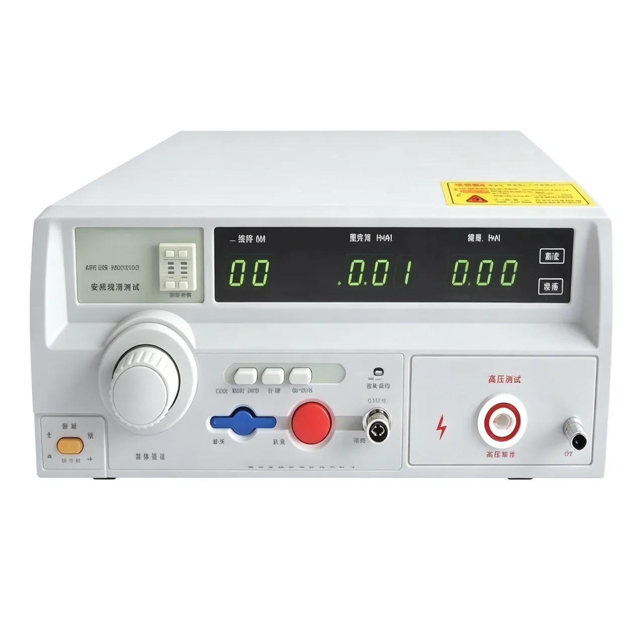
Benchtop high voltage tester seen from the front, with a green segmented readout across the upper right, a large rotary knob at the left, a row of keys with a red stop button below it and a high voltage terminal at the lower right

ZX9320SA-2 (4 models) · Electrical Safety Testers

Multi-Channel Withstand and Insulation Tester

Compact scanning safety tester with two, four or eight channels, AC and DC withstand, insulation resistance to 50 GΩ and nine-level arc detection.

Channels
Two, four or eight depending on model
AC output
0.05 to 5.00 kV, ±2%
DC output
0.05 to 6.00 kV, ±2%, not fitted to AC-only models
Leakage current
AC 0 to 10.00 mA; DC 0 to 10.00 mA on the four-channel model
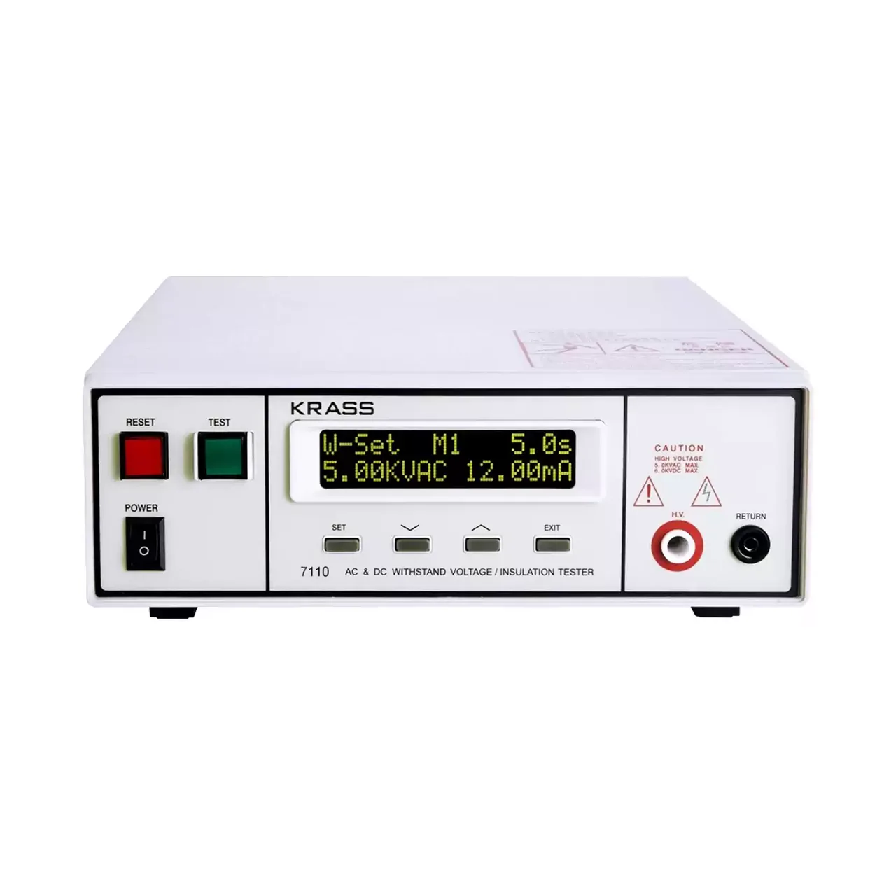
Compact programmable safety tester shown from the front with the two-line LCD at the upper left, a row of function keys beneath it and the test terminals along the lower right

7110 (8 models) · Electrical Safety Testers

Compact AC/DC Withstand Voltage and Insulation Tester

Compact programmable safety tester with 5 kV AC and 6 kV DC withstand voltage, insulation resistance to 9999 MΩ, five stored programs and PLC remote control.

AC output
0 to 5.00 kV, 12 mA
DC output
0 to 6.00 kV, 5 mA, on four of the eight models
Frequency
50 or 60 Hz, selectable
Leakage limits
0.10 to 12.00 mA AC and 0.02 to 5.00 mA DC, upper and lower set independently

Request a quotation for the LK7140P

Send the configuration you need and we will confirm availability, lead time and terms. Minimum order quantity is 1 pc.

Request for quotation

Request a quotation - LK7140P

Send the technical detail and we will confirm availability, lead time and terms. In-stock items ship within 48 hours; customized specifications typically take 2-10 days. Minimum order quantity is 1 pc.

The more of this you can give us, the fewer exchanges are needed before we can quote.
No file chosen
Datasheet, drawing, BOM or photograph. One file, up to 10 MB (PDF, Office, image or ZIP).

By submitting this form you agree that we may contact you about this enquiry. We do not sell or share enquiry data. See our privacy policy.

Items held in stock are dispatched within 48 hours of order confirmation. Customized specifications are produced to order and typically ship within 2 to 10 days. Transit time then depends on the shipping method and destination.

Request a Quote WhatsApp