Electrical Test & Measurement · Electrical Safety Testers

Five-in-One Electrical Safety Performance Tester

Touch screen safety performance tester combining withstand, ground bond, insulation, leakage and electrical parameter measurement in one sequence, in three configurations.

YP9950 (3 models) ·

Key specifications

AC withstand
300 to 5000 V, leakage 0.100 to 20.00 mA
Ground bond
AC 3 to 32 A, 0 to 600 mΩ, four-wire
Insulation resistance
DC 200 to 1000 V, 0.1 to 2000 MΩ
Leakage current
Static or dynamic, 0.000 to 20 mA
Electrical parameters
AC 5 to 300 V, 0.050 to 25.00 A, 5.0 to 6000 W
Stated accuracy
1.5% for the safety tests and 0.5% for electrical parameters, with a second page giving 1% for the safety tests
Display
Seven-inch touch LCD
Judgement
Upper and lower limits on every function, with audible and visual alarm
Interface
PC software, remote control and alarm lamp ports, all nine-pin D-type
Body
450 × 565 × 180 mm or 450 × 565 × 200 mm, about 20 kg

Appliance safety testing is a sequence, and the cost of a sequence is the handling between its steps. A tester that runs the whole sequence in one place is bought for the handling it removes, not for the number of functions on the brochure.

Product overview

One body, one touch screen, three configurations. The base model runs the five tests that a general appliance line needs, the second adds a low-voltage start test, and the third adds a direct withstand test and a separate power channel. The sequence, the limits and the judgement are the same across all three.

The front panel is deliberately sparse: a start button, a stop button, the touch screen, a pair of test terminals and an output socket. Everything that would otherwise be a knob is a field on the screen, which is what allows the same panel to serve five different tests without a row of switches for each.

How the five-in-one tester works

The instrument runs the selected tests one after another against the item that is connected. A withstand step raises an alternating voltage over a programmed ramp, holds it, and compares the leakage current with an upper and a lower limit. A bond step drives a heavy alternating current through the protective conductor and derives the resistance from the drop across it. An insulation step applies a direct voltage and reads the resistance after the charging current has settled.

The leakage step is different in kind, because the item is powered and running. The instrument measures the current that flows to earth through the enclosure or the protective conductor, in a static state or while the product is operating, and compares it with limits. The electrical parameter step measures voltage, current and power at the same terminals, so a product that passes its safety tests can be checked for consumption in the same pass.

Every step ends in a judgement rather than a number on a screen. A reading outside the limits stops the sequence and raises the alarm, which is what makes the instrument usable by an operator who is not reading the values.

How to select the right configuration

Start with the product standard and list the tests it names. If the list is withstand, bond, insulation, leakage and consumption, the base configuration covers it. A requirement to prove that the product starts at reduced voltage moves the choice up one step, and a requirement for a direct withstand test or for a power channel that is independent of the leakage measurement moves it up again.

The second question is the source. Leakage and power tests need a supply that the tester does not contain, and the rated load of those tests is set by that external unit. The instrument should be specified together with the transformer or the variable frequency supply, not before it.

The third is the bond current. The usable resistance range narrows as the bond current rises, so a product with a high bond current and a generous resistance limit may need a different arrangement rather than a higher setting.

The fourth is how results leave the bench. Ports for PC software, remote control and an alarm lamp are all provided, and a line that records results per unit will use the first of them, while a line that only needs a lamp will use the last.

Measurement limitations and selection considerations

The instrument judges against limits; it does not characterise. Where the breakdown voltage or the insulation curve is the result being sought, a tester with a recorded ramp is the right instrument, and a pass or fail unit will only report that the limit was crossed.

The leakage and power figures depend on the source feeding the test. A different transformer, a different variable frequency supply or a different lead length changes the reading, which is why a result is only comparable with another result taken on the same arrangement.

Four-wire bonding removes the lead resistance from the measurement, but it does not remove the contact resistance at the probe. Probe placement and surface condition still dominate a reading at the bottom of the range, and the same jig has to be used if readings are to be compared over time.

Finally, the configuration is fixed at the order. The extra functions of the larger models are not field upgrades, so the product standard has to be read before the model is chosen rather than after the first failed audit.

Features

  • Five safety tests plus electrical parameter measurement run in one sequence from a single screen, so a finished appliance is tested without being re-connected between instruments
  • Ground bond is measured four-wire, which removes the lead and contact resistance from the reading instead of zeroing it out afterwards
  • Withstand voltage rises and falls over a settable ramp rather than being switched, which is what a capacitive item needs
  • Leakage and power tests take their load from an external isolation transformer or variable frequency supply, so the tester is not limited by a built-in source
  • Every function has an upper and a lower limit with automatic judgement, and a failure raises both an audible and a visual alarm
  • A seven-inch touch screen shows the test item, the setpoint and the result on one page, which shortens the time an operator spends reading it
  • Three configurations cover a plain five-function bench, one with a low-voltage start test, and one that adds a direct withstand and a power channel
  • Communication ports for PC software, remote control and an alarm lamp are all on nine-pin connectors, so the cabling is standard

Technical specifications

Every value below is taken from source documentation. Where a parameter is not stated in the available material it is marked as information required rather than estimated.
AC withstand
Test typeCold-state withstand testStandard
Rated load100 VA at 5000 V and 20 mAStandard
Output voltage300 to 5000 V, resolution 10 V, ±(2% of setting + 3 V)Standard
Output frequency50 or 60 Hz, selectableStandard
RegulationBetter than 2% from no load to full loadStandard
Breakdown current range0.100 to 20.00 mA, resolution 0.001 or 0.01 mA, ±(2% of reading + 0.03 mA)Standard
Breakdown current limitsUpper and lower 0.000 to 20.00 mA, where 0.000 switches the limit offStandard
Test time0.0 or 0.1 to 999.9 s (0 = continuous), resolution 0.1 sStandard
Ground bond
Measurement methodFour-wireStandard
Open circuit output voltage12 VStandard
Output currentAC 3 to 32 A, continuously adjustable constant current, 1 A resolution, 50 or 60 HzStandard
Current accuracy±(2% of setting) over 3 to 32 AStandard
Resistance range0 to 600 mΩ from 3 to 10 A; 0 to 300 mΩ above 10 to 20 A; 0 to 200 mΩ above 20 to 32 AStandard
Resistance limitsUpper 0 to 600 mΩ; lower 0 to 600 mΩ, where 0 switches the limit offStandard
Resistance resolution1 mΩStandard
Resistance accuracy±(2% of reading + 3 mΩ)Standard
Lead zeroing0 to 200 mΩStandard
Test time0.0 or 0.1 to 999.9 s (0 = continuous), resolution 0.1 sStandard
Insulation resistance
Rated load1 VA at 1000 V and 1 mAStandard
Output voltageDC 200 to 1000 V, resolution 10 V, ±(2% of setting + 3 V)Standard
Output rippleBelow 5% into a resistive load at 1000 V and 1 mAStandard
Measurement range0.50 to 2000 MΩ, printed as 0.50 to 99.99, 999.9 and 2000 MΩ segmentsStandard
LimitsUpper 0 or 1 to 2000 MΩ, where 0 switches it off; lower 1 to 2000 MΩStandard
Resolution0.1 MΩStandard
Accuracy below 100 MΩ±(5% of reading + 0.5 MΩ)Standard
Accuracy from 101 to 2000 MΩ±(10% of reading + 5 MΩ)Standard
Resistance compensationAbove 30 MΩStandard
Leakage current
Leakage typeStatic or dynamicStandard
Output voltage setting rangeAC 0 to 300 VStandard
Output voltage measurementAC 5 to 300 V, resolution 1 V, ±(2% of reading + 3 V)Standard
Leakage limitsUpper and lower 0.000 to 20 mA, where 0.000 switches the limit offStandard
Leakage resolution0.001 or 0.01 mAStandard
Leakage accuracy±(2% of reading + 0.03 mA)Standard
Rated loadSet by the external isolation transformer or variable frequency supply, not by the testerStandard
Test time0.0 or 0.5 to 999.9 s (0 = continuous), resolution 0.1 sStandard
Electrical parameters
Voltage measurementAC 5 to 300 V, resolution 1 V, ±(0.5% of reading + 0.5% of range)Standard
Current measurement0.050 to 25.00 A, resolution 0.001 or 0.01 A, ±(0.5% of reading + 0.5% of range)Standard
Power range5.0 to 6000 W, resolution 0.1 or 1 W, ±(0.5% of reading + 0.5% of range)Standard
Power limitsUpper and lower 0 to 6000 W, where 0 switches the limit offStandard
Power sourceSet by the external isolation transformer or variable frequency supplyStandard
Test time0.0 or 0.5 to 999.9 s (0 = continuous), resolution 0.1 sStandard
Low-voltage start, 9960 and 9970
Voltage measurementAC 5.0 to 300.0 V, resolution 1 V, ±(0.5% of reading + 0.5% of range)Standard
Current range0.050 to 25.00 A, resolution 0.001 or 0.01 A, ±(0.5% of reading + 0.5% of range)Standard
Current limitsUpper and lower 0.000 to 25.00 AStandard
Delay time0.2 to 999.9 sStandard
Test time0.0 or 0.5 to 999.9 s (0 = continuous), resolution 0.1 sStandard
Supply, body and environment
Input supplyAC 220 V ±10%, 50 or 60 Hz ±5%Standard
Idle powerAbout 30 WStandard
Dimensions450 × 565 × 180 mm or 450 × 565 × 200 mm, excluding feet; the dimension drawing gives 450 × 565 × 200 mmStandard
WeightAbout 20 kgStandard
Operating environment0 to 40 °C, 20 to 80% RHStandard
Standard accessoryClass II test probeStandard
Optional accessoryThree-colour alarm lamp, listed for all three modelsOptional
Calibration certificateNot stated in the materialInformation required
Ingress protectionNot stated in the materialInformation required

Available models

Selection table
Model Configuration Key ranges Availability
YP9950 Five functions Withstand, ground bond, insulation, leakage and electrical parameters The general-purpose configuration
YP9960 Six functions As YP9950 plus a low-voltage start test For products that must be started at reduced voltage
YP9970 Seven functions AC and DC withstand, insulation, leakage, power, electrical parameters and low-voltage start For a direct withstand test or a separate power channel

Customization

  • Alarm lamp supplied as an accessory for a line-side indication
  • Wiring prepared for a particular isolation transformer or variable frequency supply

Certification and compliance

Certification documents not yet supplied

Certifications are only published once a certificate copy can be produced, so this section is deliberately empty rather than populated with assumed approvals. Tell us which approvals your application requires and we will confirm what is available for this instrument.

Parameters still to be confirmed

The following are required for a complete specification but are not stated in the documentation supplied to us. They are listed rather than estimated:

  • Whether the safety test accuracy is 1.5% as the feature text states or 1% as the model table states
  • Which body height is correct, since the general table gives 180 mm and 200 mm and the dimension drawing gives 200 mm
  • Whether the ground bond output reaches 30 A as the model table states or 32 A as the detailed table states
  • Whether the power test belongs to the five-function configuration, since the detailed tables are labelled for the five-function model but include a power section and a low-voltage start section
  • What the rated capacity of the external isolation transformer or variable frequency supply has to be for a given product
  • Calibration certificate availability and the standard it would be issued against
  • Warranty period and its terms
  • The full packing list, since only the test probe and the optional alarm lamp are identified
  • Ingress protection rating, which the material does not give

Frequently asked questions

Does the tester supply the mains for the leakage and power tests?

No. Those functions take their load from an external isolation transformer or a variable frequency supply, and the rated load is decided by that unit rather than by the tester. The instrument measures the voltage, current and power at its terminals and applies the limits; the source has to be specified separately, which is why it belongs in the enquiry.

What is the low-voltage start test for?

It checks that a product starts and runs at a reduced supply voltage, which is a requirement for some appliances and motor-driven products. It measures the voltage and current during the start and compares them with limits after a settable delay, so a product that draws too much current or fails to start is caught on the line rather than at the end user.

Which configuration should be quoted?

The five-function model covers withstand, ground bond, insulation, leakage and electrical parameters. The six-function model adds the low-voltage start test, and the seven-function model adds a direct withstand test and a separate power channel. Ask which of those three extra functions the product standard actually calls for; the rest of the specification is shared.

What has to be confirmed before a quotation?

The functions the product standard requires, which fixes the configuration; the leakage and power source that will feed the test, since the tester does not include one; the ground bond current, because the resistance range narrows as that current rises; and whether the results have to be sent to a PC or only indicated on the line.

Related products

Other models in the same range

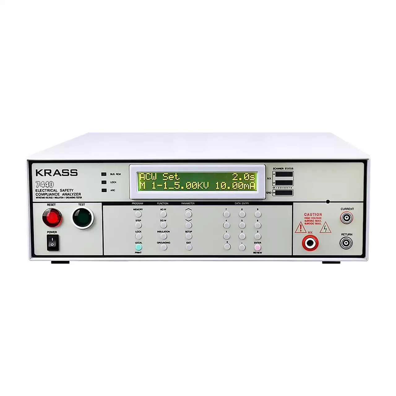
Benchtop safety compliance analyser seen from the front, with a backlit dot matrix display at the upper centre, a red reset button and a green test button at the left, function keys and a numeric keypad below the display, and current and return terminals at the right

7440 (4 models) · Electrical Safety Testers

Four-in-One Electrical Safety Compliance Tester

Bench safety compliance analyser combining AC and DC withstand, insulation resistance and, on the top model, ground bond testing, with stored programs and a matrix scanner interface.

AC withstand
0 to 5 kV, up to 40 mA
DC withstand
0 to 6 kV, up to 9999 μA
Insulation resistance
100 to 1000 V DC, 1 to 9999 MΩ
Ground bond
3 to 40 A, 0 to 600 mΩ, on 7440 only
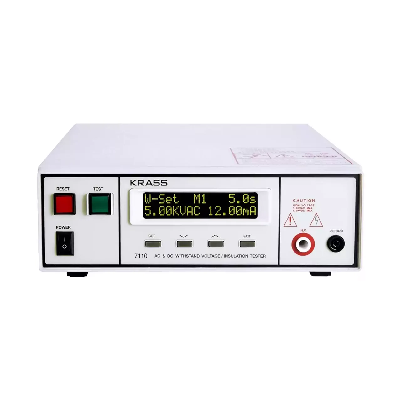
Compact programmable safety tester shown from the front with the two-line LCD at the upper left, a row of function keys beneath it and the test terminals along the lower right

7110 (8 models) · Electrical Safety Testers

Compact AC/DC Withstand Voltage and Insulation Tester

Compact programmable safety tester with 5 kV AC and 6 kV DC withstand voltage, insulation resistance to 9999 MΩ, five stored programs and PLC remote control.

AC output
0 to 5.00 kV, 12 mA
DC output
0 to 6.00 kV, 5 mA, on four of the eight models
Frequency
50 or 60 Hz, selectable
Leakage limits
0.10 to 12.00 mA AC and 0.02 to 5.00 mA DC, upper and lower set independently
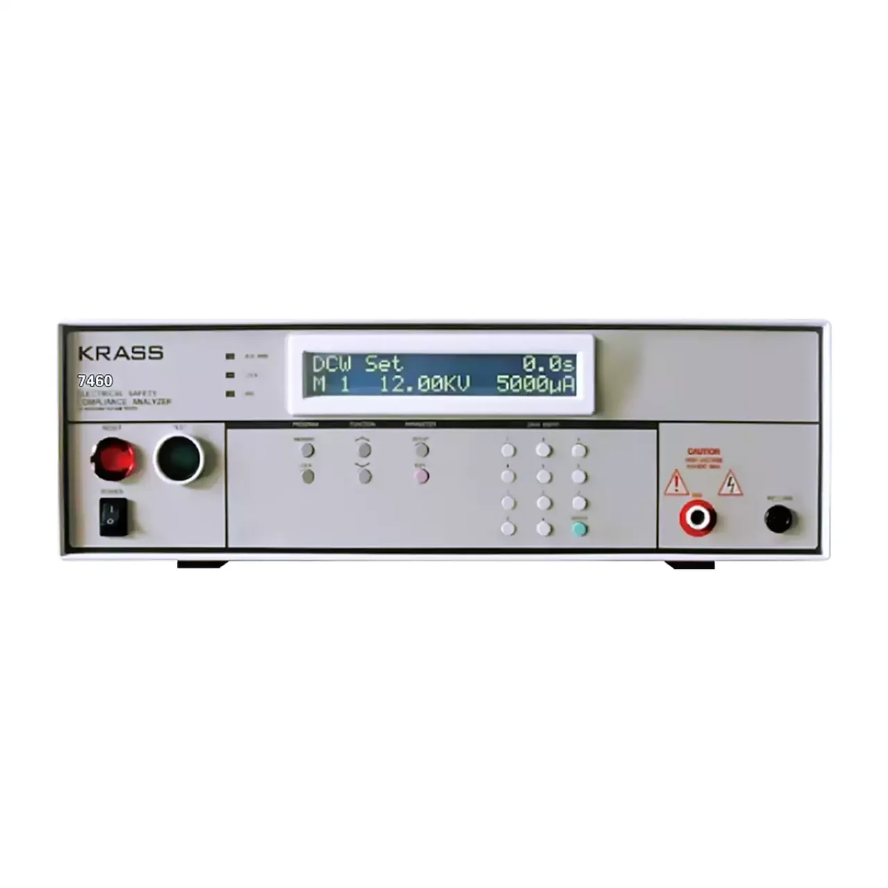
Benchtop high voltage tester seen from the front, with a backlit two-line display at the upper centre, a red reset button and a green test button at the left, function keys and a numeric keypad beneath the display, and high voltage and return terminals at the right

7460 (2 models) · Electrical Safety Testers

10 kV Programmable Withstand Voltage Tester

Programmable high voltage withstand tester in an alternating and a direct version, with a regulated output, fifty linked program groups, arc detection and remote control.

AC output
0.00 to 10.00 kV at 10 mA, on 7460
DC output
0.00 to 10.00 kV at 5000 μA, on 7462
Voltage resolution
0.01 kV
Leakage limits, AC
Upper 0 to 10.0 mA, lower 0.1 to 10.0 mA

Request a quotation for the YP9950

Send the configuration you need and we will confirm availability, lead time and terms. Minimum order quantity is 1 pc.

Request for quotation

Request a quotation - YP9950

Send the technical detail and we will confirm availability, lead time and terms. In-stock items ship within 48 hours; customized specifications typically take 2-10 days. Minimum order quantity is 1 pc.

The more of this you can give us, the fewer exchanges are needed before we can quote.
No file chosen
Datasheet, drawing, BOM or photograph. One file, up to 10 MB (PDF, Office, image or ZIP).

By submitting this form you agree that we may contact you about this enquiry. We do not sell or share enquiry data. See our privacy policy.

Items held in stock are dispatched within 48 hours of order confirmation. Customized specifications are produced to order and typically ship within 2 to 10 days. Transit time then depends on the shipping method and destination.

Request a Quote WhatsApp