- Resistance range
- 10 µΩ to 20 kΩ
- Basic accuracy
- 0.05%, with the detailed specification in the operating manual
- Test current
- ≤ 100 mA
- Display
- 4.3 inch IPS colour LCD, 480 × 272, 4½ digit readings
- Reading rate
- 15 readings per second on the fast setting, 8 on the slow setting, single channel
- Parameters
- Line resistance Rab, Rbc and Rca; phase resistance Ra, Rb and Rc; spread and unbalance for both
- Test terminals
- Four-terminal Kelvin, three channels, single or three-channel scan
- Interfaces
- RS232C, HANDLER and USB host as standard; RS485 optional with Modbus
- Environment
- 0 to 40 °C, up to 90% RH without condensation
- Body
- 215 × 86 × 330 mm, about 4.0 kg
A three-phase winding is symmetrical by design, and almost every fault that matters breaks that symmetry. The tester exists to measure the three resistances the same way, at the same moment, and to turn the comparison into a decision.
Product overview
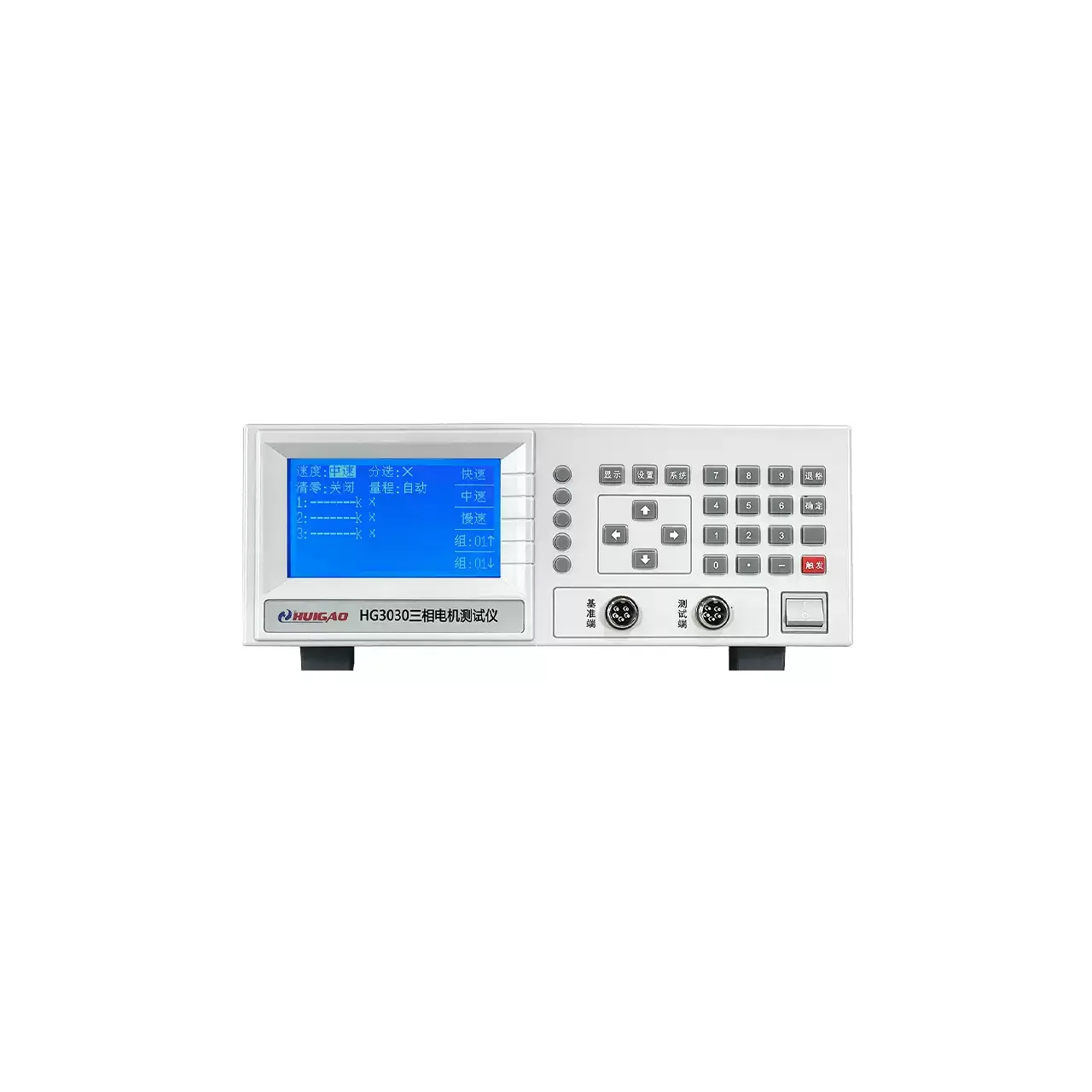
One instrument, three Kelvin channels, one colour screen. Each channel forces a current through a winding and senses the voltage across it separately, so what appears on the display is the winding and not the leads.
The screen is arranged around the comparison rather than around a single reading: line resistances in one column, phase resistances in the next, and the spread and unbalance for both underneath. The sorting result is on the same screen, so an operator does not look away to find it.
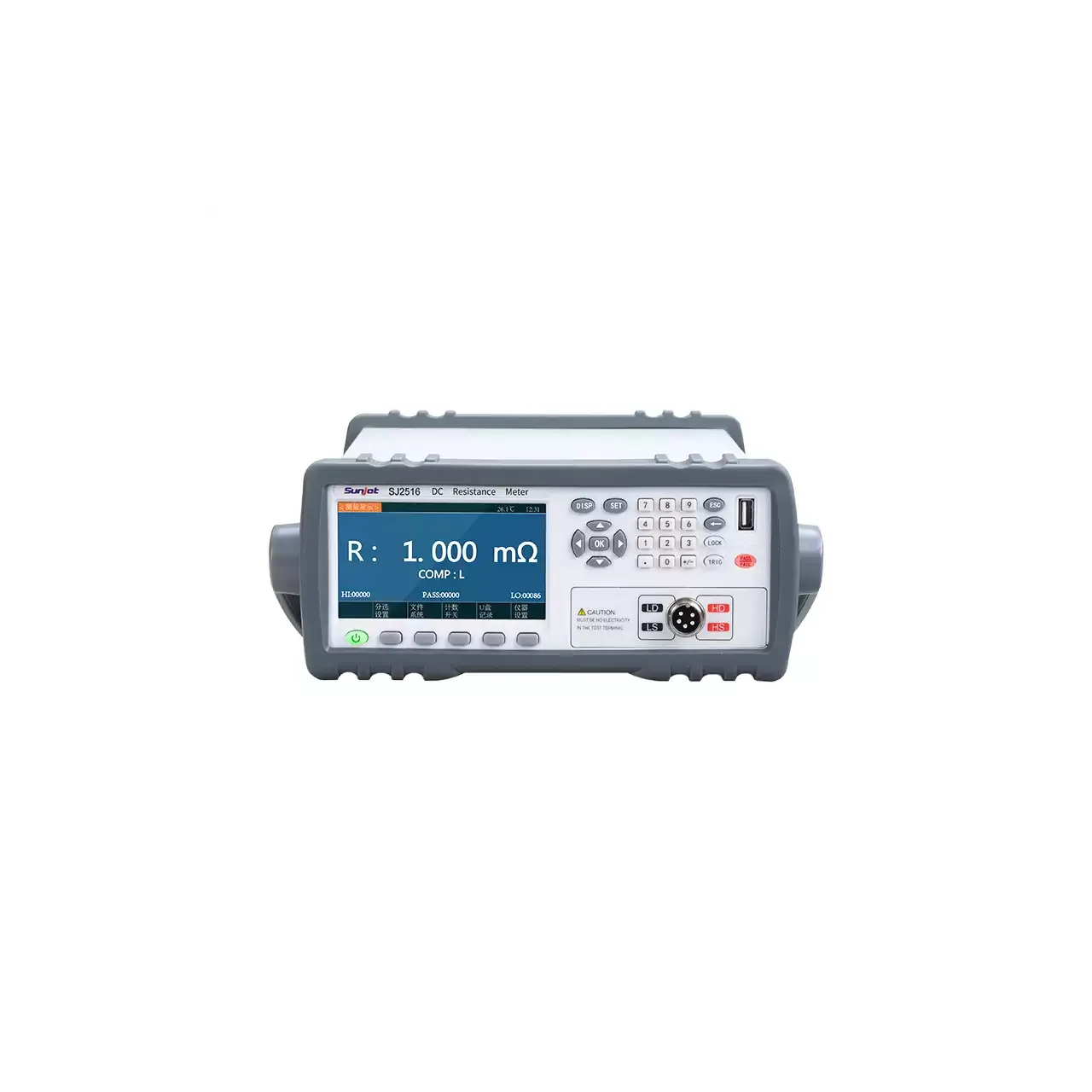
The case is a bench instrument with the input sockets along the lower edge and the keypad to the right. It is meant to sit at a test station, not to be carried to a motor in the field.
How the tester measures a winding
Resistance is measured by forcing a known current and reading the voltage that appears across the winding. The four-terminal connection is what makes this work at small values: one pair of leads carries the current, a second pair senses the voltage directly at the winding terminals, and the voltage drop along the current leads never enters the reading.
Three channels are measured in turn or in a scan. Because the same current source and the same conversion path are used for all three, the readings are comparable with each other in a way that three separate measurements are not. That comparability is the point: the unbalance is a difference between readings, and a difference is only meaningful if the readings share a reference.
The instrument converts between line and phase resistance according to the connection setting, computes the spread as the difference between the highest and lowest of the three, and expresses the unbalance as a percentage. Which of the two is judged is a setting, because different acceptance documents use different ones.
Temperature compensation works from a measured or entered ambient and converts the reading to a stated reference temperature. Winding resistance rises with temperature, so a motor tested warm will read high against a cold specification unless the reading is referred back.
How to select the right configuration
The range decides whether the instrument fits at all. A small servo winding and a large stator are at opposite ends of the same scale, and the bottom of the range is where the four-terminal connection and the zeroing behaviour matter most.
The acceptance criterion decides the comparator setup. If the drawing states a percentage unbalance, judge on unbalance; if it states a maximum difference in ohms, judge on spread. Setting both and judging on one is a common source of argument at the station.
The line decides the interfaces. A manual station needs the display and the buzzer. A station with a handler needs the sorting signals. A line that records results needs the serial link or a USB stick, and a line that scans more than three channels needs the optional RS485 with several instruments cascaded.
The throughput decides the rate. The fast setting suits a line that tests every motor; the slow setting suits a laboratory check where the reading is recorded.
Measurement limitations and selection considerations
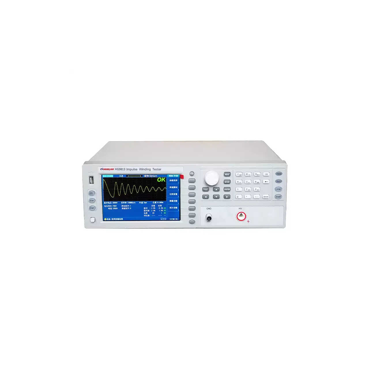
The instrument measures resistance, not inductance or insulation. A shorted turn in a winding may barely change its DC resistance, especially in a large motor, so a resistance unbalance within limits does not clear a winding of every fault. An impulse or surge test is the method for turn-to-turn insulation, and it answers a different question.
The reading depends on temperature, and the compensation only removes that dependence if the temperature used is the winding temperature rather than the air temperature. A motor that has just run is warmer than the room, and the difference is large enough to matter.
Kelvin clips have to be on clean metal. Paint, oxide and varnish at the terminal add resistance in the current path or, worse, in the sense path, and a bad sense connection shows up as a reading that drifts or jumps between scans.
Finally, the unbalance figure is only as good as the three readings being simultaneous in condition. A winding that is still cooling between the first and third channel will show an unbalance that is an artefact of the test sequence rather than of the motor.
Every value below is taken from source documentation. Where a parameter is not stated in the available material it is marked as information required rather than estimated.