Electrical Test & Measurement · Insulation Resistance Testers

High-Speed Wide-Range Insulation Resistance Tester

Bench insulation resistance meter with a voltage range from 1 V, resistance to 100 TΩ, three measuring speeds, five-bin sorting and 600 stored records on the wide-range model.

HG7683 (2 models) ·

Key specifications

Test voltage
1 to 1000 V continuous on the wide-range model; 10 to 1000 V settable on the other
Resistance range
500 Ω to 100 TΩ on the wide-range model; 100 kΩ to 1 TΩ on the other
Current range
1 pA to 2 mA on the wide-range model; 0.001 to 200.0 µA on the other
Accuracy
1% while resistance is below 10 GΩ and current above 10 nA; ±3% ±3 digits below 1 TΩ and ±8% ±3 digits above it on the other model
Speed
40, 15 and 5 readings per second in three steps; about 6.7 per second on the other model
Input resistance
10 kΩ or 1 MΩ, switchable, on the wide-range model
Sorting
Five comparator outputs, low, three bins and high; one pass or fail bin on the other model
Storage
100 internal records and 500 on USB, on the wide-range model
Display
480 × 272 colour screen; four significant digits on the other model
Body
280 × 88 × 320 mm at 4 kg; 350 × 300 × 105 mm at about 3 kg for the other model

Two instruments under one page, and they are not two trim levels of the same thing. One is a fast wide-range meter built to sort parts on a line; the other is a conventional bench instrument that answers a single question. The choice between them is a choice of task.

Product overview

The wide-range model covers resistance from hundreds of ohms to a hundred teraohms, at a voltage that starts at one volt, with three speeds, five sorting outputs and six hundred stored records. It is a production and laboratory instrument in a half-rack case.

The conventional model covers a narrower resistance band at a fixed lower voltage limit, with a pass or fail judgement and optional interfaces. It is smaller, lighter and simpler, and it is the right instrument where the test is one point rather than a distribution.

Both apply a direct voltage, measure the leakage current and derive resistance from the ratio, and both provide open-circuit zeroing to remove the residual of the fixture.

How the meter works

The output is raised to the programmed voltage and the current that flows is measured. Resistance follows from the ratio, which means the highest resistance the instrument can report is set by the smallest current it can resolve, and the accuracy falls away as that floor is approached.

The wide-range model changes its input resistance between two values. That is not a range switch in the ordinary sense: it changes the impedance the instrument presents to the item, and therefore how quickly the charging current decays to the leakage level. A low input resistance charges a capacitive item quickly and gives a reading sooner; a high one draws less from the source and suits the top of the resistance range.

The three speeds trade time against noise. Averaging over more readings reduces the scatter on a high-resistance measurement, and the fastest setting is for a line where the pass limit is far from the reading and the scatter does not matter.

Sorting compares the result with stored limits and drives one of five outputs, so a handler can route a part to a bin rather than only stopping the line.

How to select the right model

Begin with the resistance band. A test that has to distinguish an open circuit from a good insulator at the top of the range needs the wide-range model, because the conventional one stops a hundred times lower.

Then the voltage. If the test has to run below ten volts, only the wide-range model reaches it. If the standard calls for a few hundred volts, both do.

Then the throughput. A line that tests every part needs the fast step and the sorting outputs; a laboratory that tests a sample needs neither, and the conventional model is the simpler purchase.

Then the interface. GPIB appears on one page and not on another, so a bench that is already wired for it has to have that point settled in writing before the order.

Measurement limitations and selection considerations

The accuracy figure is conditional, and the condition is the interesting part. It applies where the resistance is below ten gigohms and the current above ten nanoamps; outside that, the error grows because the current channel is working near its floor. A single percentage quoted without the condition would be true only in the middle of the range.

At the top of the range the measurement becomes an environmental one. Surface leakage, humidity, the insulation of the leads and the geometry of the item all contribute currents of the same order as the one being measured, and no instrument can separate them without a guard, shielded leads and a controlled environment.

Insulation resistance is not dielectric strength. This instrument measures leakage at a voltage below breakdown; a withstand test measures survival at a higher voltage. The two are separate tests, and a good insulation reading does not predict a withstand result.

The two models differ in size as well as capability, and the footprints are not interchangeable. A bench laid out for one will not necessarily take the other without moving what is around it.

Features

  • A resistance range that starts in the hundreds of ohms and reaches a hundred teraohms, so one instrument covers a busbar joint and a polymer film
  • A test voltage that starts at one volt, which allows a component to be checked at its own rating rather than at a standard test level
  • A switchable input resistance of 10 kΩ or 1 MΩ, which changes how fast a capacitive item charges and therefore how quickly a stable reading is available
  • Three measuring speeds with averaging up to 255 readings, so a noisy high-resistance measurement can be traded against time
  • Five comparator outputs, low, three bins and high, which lets a line sort parts into grades rather than only accept or reject them
  • Six hundred stored records, a hundred internal and five hundred on a USB stick, so a run can be kept without a computer
  • A colour screen with a menu structure, which shows resistance, current, voltage and the sorting state at once
  • An open-circuit zero that removes the residual of the fixture and the leads from the reading

Technical specifications

Every value below is taken from source documentation. Where a parameter is not stated in the available material it is marked as information required rather than estimated.
Measurement
ParametersResistance and current on the wide-range model; voltage, resistance and current on the otherStandard
Resistance rangeHG7683 500 Ω to 100 TΩ; HG2683 100 kΩ to 1 TΩ, printed as 1 × 10⁵ to 1 × 10¹² ΩStandard
Current rangeHG7683 1 pA to 2 mA; HG2683 0.001 to 200.0 µAStandard
Resistance accuracyHG7683 1% where resistance is below 10 GΩ and current above 10 nA; HG2683 ±3% ±3 digits below 1 TΩ and ±8% ±3 digits at or above itStandard
Current accuracyHG7683 1% under the same two conditions; HG2683 not stated separatelyInformation required
Voltage accuracyHG7683 0.5%, with the detailed table referred to but not supplied; HG2683 display ±1%, no-load output ±1% of setting ±1 VInformation required
Charge current limit10 mA on the wide-range modelStandard
ZeroingOpen-circuit zero on both modelsStandard
Reference standardNot stated in the materialInformation required
Ranges and timing
RangesSeven, automatic or manual, on the wide-range model; automatic or manual on the otherStandard
SpeedHG7683 40, 15 and 5 readings per second; the model card gives 45 for the fast stepInformation required
HG2683 speedAbout 6.7 readings per second, 159 ms per readingStandard
Averaging1 to 255 readings on the wide-range modelStandard
Charge time0 to 1000 s on the wide-range modelStandard
Measurement delay0 to 60 s on the wide-range modelStandard
Test time0 to 999.9 s on HG2683, where zero gives continuous measurementStandard
TriggerInternal, manual, external and bus on the wide-range model; continuous or single on the otherStandard
Sorting and storage
ComparatorLow, bin 1, bin 2, bin 3 and high on the wide-range model; pass or fail on HG2683Standard
Sort limitsX.XXX to XXX.X GΩ on HG2683, where zero disables sortingStandard
MemoryFour groups on HG2683; 100 internal and 500 external records on the wide-range modelStandard
BuzzerPass, fail or off on HG2683Standard
Barcode inputA barcode connector appears on the rear panel of the wide-range model and is absent from the interface tableInformation required
Interface, supply and physical
Interfaces as tabledHANDLER, RS232C, USB host and USB device on the wide-range model; HANDLER and RS232 optional on HG2683Standard
Interfaces as illustratedRS232C, USB TMC, USB CDC, HANDLER and GPIB on a dedicated interface page, with GPIB also marked on the rear panelInformation required
Supply220 V ±10%, 50 or 60 Hz ±5%Standard
Environment0 to 40 °C, below 90% relative humidityStandard
DimensionsHG7683 280 × 88 × 320 mm; HG2683 350 × 300 × 105 mmStandard
Weight4.0 kg and about 3 kgStandard
Supplied accessoriesA resistance test lead listed for both models; no other carton contents are givenStandard
Ingress protectionNot stated in the materialInformation required

Available models

Selection table
Model Configuration Key ranges Availability
HG7683 Wide range, high speed, five-bin sorting, internal and USB storage 1 to 1000 V; 500 Ω to 100 TΩ; 1 pA to 2 mA; 40, 15 and 5 readings per second The model for a line that sorts parts or for a laboratory that needs the wide range
HG2683 Conventional model with pass or fail judgement and optional interfaces 10 to 1000 V; 100 kΩ to 1 TΩ; 0.001 to 200.0 µA; about 6.7 readings per second The simpler model for a single-point insulation check

Customization

  • The interface set on HG2683, which is optional rather than fitted
  • The sorting limits and memory groups, configured at set-up
  • The test lead, listed for both models but not described further

Certification and compliance

Certification documents not yet supplied

Certifications are only published once a certificate copy can be produced, so this section is deliberately empty rather than populated with assumed approvals. Tell us which approvals your application requires and we will confirm what is available for this instrument.

Parameters still to be confirmed

The following are required for a complete specification but are not stated in the documentation supplied to us. They are listed rather than estimated:

  • The detailed voltage accuracy table that the wide-range model refers to but the material does not include
  • Whether the fast measuring step is 40 or 45 readings per second
  • Whether GPIB and the barcode connector are fitted, since the interface table, the interface page and the rear panel disagree
  • The current accuracy of HG2683, which is not stated separately
  • The conditions behind the HG7683 accuracy figure, which are printed identically for resistance and current
  • The measured voltage readback accuracy during a test on the wide-range model
  • The maximum capacitive load that can be charged, and the charge time behaviour at the limit
  • The standard the accuracy is quoted against, and calibration certificate availability
  • The full contents of the shipping carton
  • Ingress protection and warm-up time
  • Warranty period and its terms

Frequently asked questions

What does the switchable input resistance change?

It changes the impedance the instrument presents to the item, and with it the time constant of the charging current. A low input resistance charges a capacitive item faster and gives a reading sooner; a high one draws less current from the source and suits a high-resistance measurement. The practical effect is a trade between speed and the ability to resolve very small currents, which is why the setting is on the front panel rather than fixed.

Why is the accuracy qualified by a resistance and a current condition?

Because the figure only holds where both the voltage and the current are comfortably measurable. Below ten nanoamps the current channel is near its floor, and above ten gigohms the resistance is inferred from a very small current, so the error grows. The unqualified figure would be true only in the middle of the range, which is the part a buyer is least likely to be worried about.

What has to be confirmed before a quotation?

The highest resistance that must be distinguished from an open circuit; the test voltage, and whether it has to go below ten volts; how many readings per second the line needs; whether parts are sorted into bins or only passed or failed; whether GPIB is required, since the interface table and the interface page disagree; and whether records have to be stored without a computer.

Related products

Other models in the same range

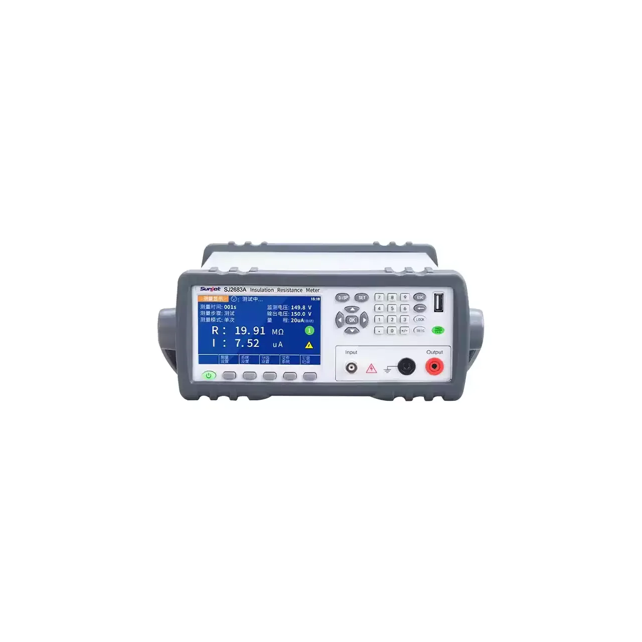
Benchtop insulation resistance meter in a grey case with a carrying handle, a colour screen at the left showing resistance and current readings above a row of soft keys, a numeric keypad at the right and three terminals labelled Input and Output below it

SJ2682A (6 models) · Insulation Resistance Testers

Programmable Digital Insulation Resistance Meter

Benchtop insulation resistance meter with programmable direct voltage from 0.5 V, resistance ranges to 100 PΩ on the top model, micro-current measurement from 0.1 fA and four-bin sorting.

Resistance range
10 kΩ to 1 TΩ on the entry model; 0.1 kΩ to 100 PΩ on the top model
Test voltage
Direct, 10 to 1000 V in 1 V steps, or 0.5 to 1000 V in 0.1 V steps by model
Current range
1 mA down to 0.01 pA, 0.01 nA, 0.01 pA or 0.1 fA by model
Resistance accuracy
±2% or ±3% below 1 GΩ, ±5% above 1 GΩ, ±10% above 1 TΩ
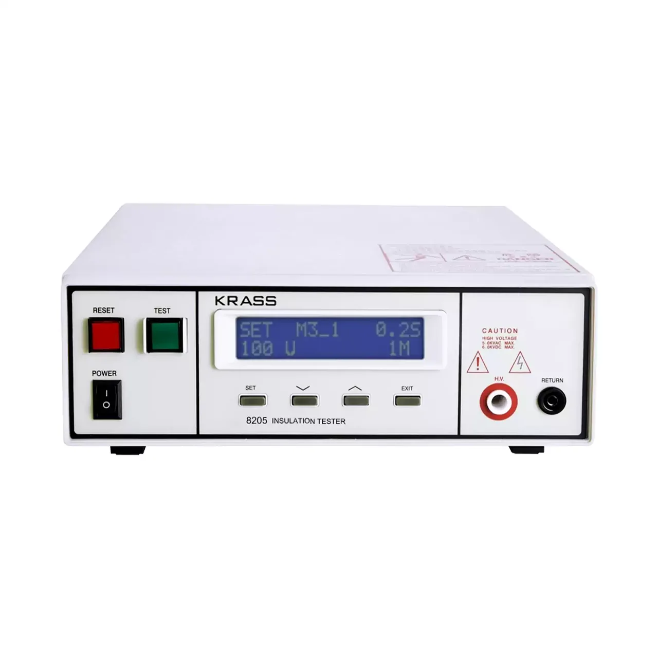
Bench insulation tester in a white case seen from the front, with a two-line liquid crystal display in the centre showing a set voltage and a resistance limit, a red reset button and a green test button at the left, four small keys below the display and a red high-voltage terminal beside a black return terminal at the right

8205 (2 models) · Insulation Resistance Testers

Insulation Resistance and Battery Short-Circuit Tester

Bench insulation tester with a 100 to 1000 V direct output, resistance measurement to 9999 MΩ, programmable rise and test times, a PLC remote interface and automatic discharge.

Output voltage
100 to 1000 V DC, 1 V resolution, ripple below 2%
Resistance range
1 MΩ to 9999 MΩ, automatically selected
Resistance accuracy
±(2% of setting + 2 counts) from 1 to 1000 MΩ; ±(3% + 2 counts) to 9999 MΩ
Rise time
1.0 to 999.9 s in the parameter table; 0.1 to 999.9 s in the description, both carried
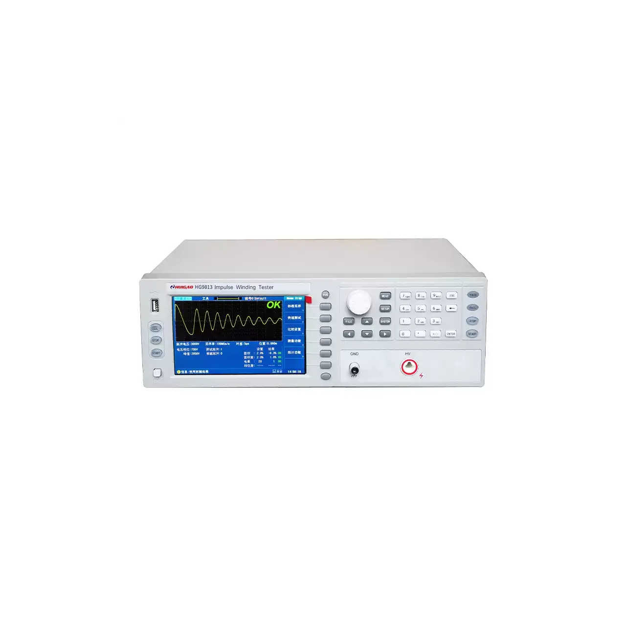
Bench winding insulation tester in a light grey case, with a 7-inch colour LCD at the left showing two overlaid pulse waveforms and a green OK result, a column of soft keys beside the screen, a rotary knob and numeric keypad at the right, and a ground terminal beside a red high-voltage terminal at the lower right

HG9813 (4 models) · LCR Meters

Winding Insulation Tester

Four impulse winding testers reaching up to 10 kV, with corona analysis, high-speed waveform capture, a 7-inch colour display and pass or fail outputs for inter-turn insulation testing of coils and windings.

Pulse voltage
100 V to 3000 V on HG9813, 100 V to 5000 V on HG9815, 200 V to 6000 V on HG9816 and 300 V to 10,000 V on HG9810, all in 10 V steps at 5% ±10 V
Pulse energy
0.09 J on HG9813, 0.25 J on HG9815, 0.36 J on HG9816 and 0.5 J on HG9810
Inductance range
≥10 µH on HG9813, HG9815 and HG9816; ≥50 µH on HG9810
Test speed
15 per second on HG9813 and HG9815, 12 on HG9816 and 8 on HG9810

Request a quotation for the HG7683

Send the configuration you need and we will confirm availability, lead time and terms. Minimum order quantity is 1 pc.

Request for quotation

Request a quotation - HG7683

Send the technical detail and we will confirm availability, lead time and terms. In-stock items ship within 48 hours; customized specifications typically take 2-10 days. Minimum order quantity is 1 pc.

The more of this you can give us, the fewer exchanges are needed before we can quote.
No file chosen
Datasheet, drawing, BOM or photograph. One file, up to 10 MB (PDF, Office, image or ZIP).

By submitting this form you agree that we may contact you about this enquiry. We do not sell or share enquiry data. See our privacy policy.

Items held in stock are dispatched within 48 hours of order confirmation. Customized specifications are produced to order and typically ship within 2 to 10 days. Transit time then depends on the shipping method and destination.

Request a Quote WhatsApp