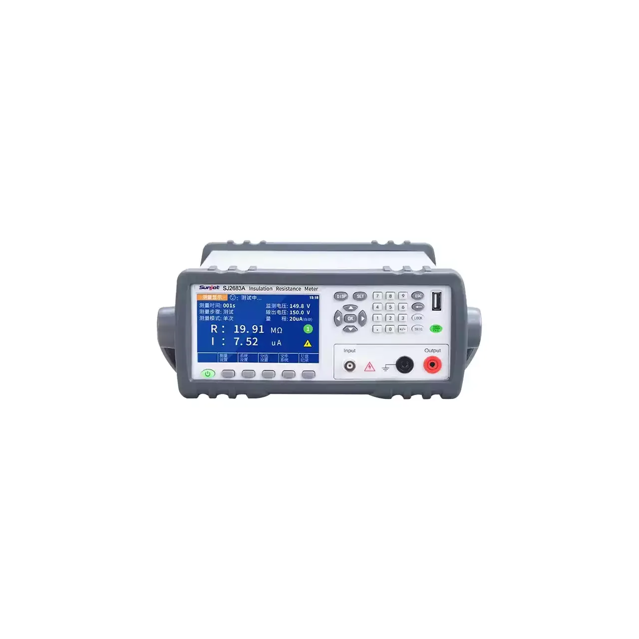
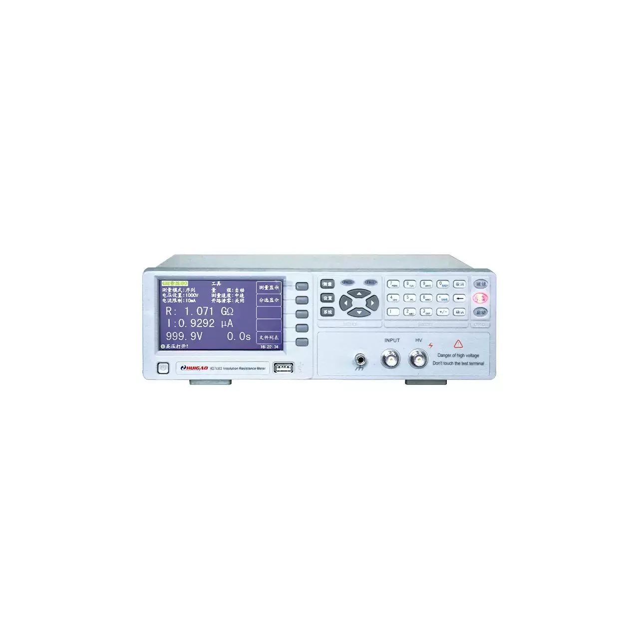
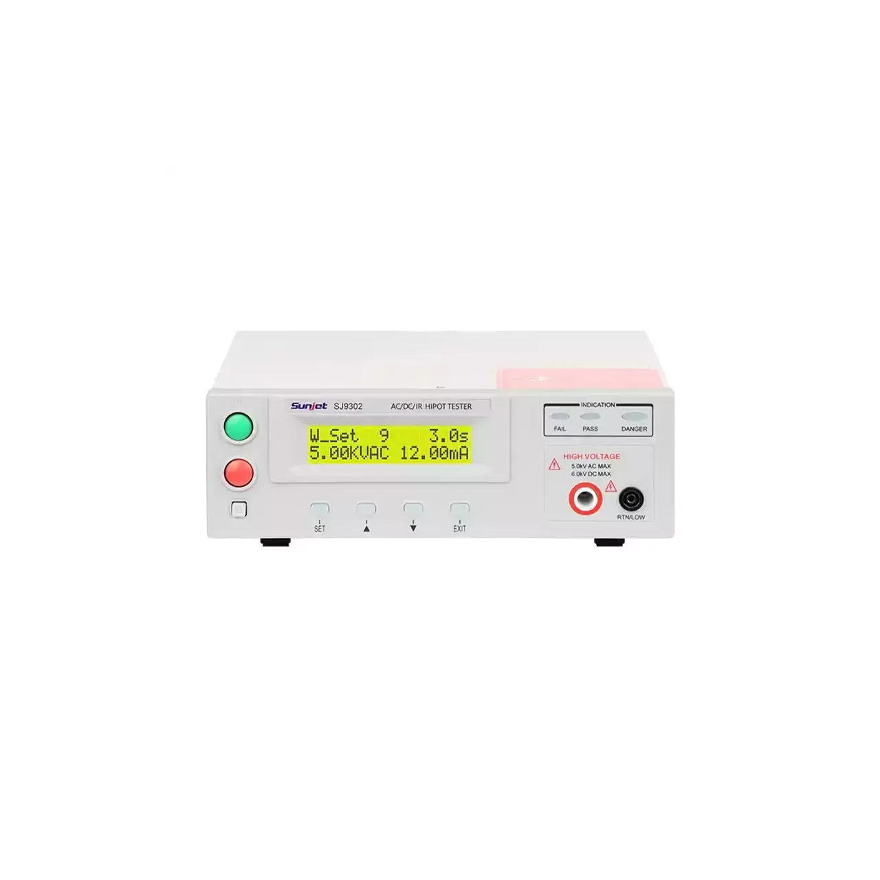
- Resistance range
- 10 kΩ to 10 TΩ on the programmable 1 kV model; 100 kΩ to 10 TΩ on the manual 1 kV model
- Test voltage
- 0.5 to 1000 V continuously on the programmable models; fixed taps from 10 V on the manual ones
- Leakage current
- 10 pA to 1 mA on the programmable models
- Accuracy
- ±2% above 10 nA, ±5% below 10 nA and ±10% below 1 nA
- Voltage accuracy
- ±0.25% ±0.5 V above 10 V; ±1% ±0.5 V at or below 10 V
- Speed
- Under 45 ms per reading fast and 85 ms slow on the programmable models
- Timing
- Charge time and test time each programmable from 0 to 999 s
- Memory
- Five settings held internally or on a USB stick
- Sorting
- PASS1, PASS2, PASS3 and FAIL comparator outputs
- Body
- 361 × 107 × 264 mm, about 4.6 kg, in a bench case with a two-line backlit display
A family of six instruments built on two different ideas. Three set their voltage at fixed taps and range by hand; three set it continuously and range themselves, and one of those sits between the groups. The choice is decided by how the test is set up, not by the measuring circuit alone.
Product overview
The manual models offer a handful of voltage taps, a manual range and a pass or fail judgement, and three of them have no interface at all. They are the simpler purchase where the test is a single point at a standard voltage.
The programmable models offer a continuous voltage from half a volt, a programmable charge time and test time, automatic ranging with a lock, three comparator limits with three pass outputs, five stored settings and a full interface set with a command language.
The microprocessor-controlled model in the middle keeps automatic ranging and a PLC interface but uses a fixed set of voltages and a narrower resistance range, which makes it the least expensive way to get an interface.
How the tester works
A direct voltage is applied across the item, and the current that flows is measured on a sense channel. Resistance is the ratio of the two, computed by the instrument, and the current itself is available as a second reading. That second reading is often the more informative of the two: a low resistance caused by a surface path and one caused by a defect in the material look the same as a number but behave differently as the voltage changes.
On the programmable models the voltage, the charge time and the test time are all set before the test. The charge time lets a capacitive item draw its inrush before the measurement window opens; the test time holds the voltage for the period the procedure requires. Ranging is automatic but locks once the reading settles, which prevents the display from stepping between ranges on a value near a boundary.
The comparator compares the result with up to three limits and drives separate outputs, so a handler can sort parts into grades rather than only stopping on a failure.
How to select the right model
The first question is whether the voltage has to be continuous. A procedure built around standard test voltages is served by the taps; a procedure that tests a component at its own rating, or sweeps the voltage, needs the continuous output.
The second is the resistance ceiling, which follows from the current floor. The programmable 1 kV model reaches the highest resistance in the family; the others stop lower, and the difference is a decade rather than a few per cent.
The third is the interface. RS485, SCPI and the handler output exist only on the programmable models, and a line that is already wired for one of them should not have to add a converter.
The fourth is sorting. A three-limit comparator with three pass outputs is a production feature; a pass or fail judgement is enough for a bench check, and paying for more than the test needs is the commonest over-specification in this category.
Measurement limitations and selection considerations
The measurement floors are model-specific and they matter. The programmable models start at ten kilo-ohms, which is high for a fault check: a shorted or heavily contaminated item may read below the floor and be reported as out of range rather than as a low resistance.
The accuracy is banded by current, not by resistance, and the bands are wide apart. A measurement below a nanoamp carries a ten per cent tolerance, which is not a figure to set a tight limit against. The limit should be placed where the band is comfortable, or the uncertainty accepted.
The display is a two-line character panel rather than a graphical screen, so a sweep or a trend is not shown. Where a curve is needed, the reading has to be collected over the interface.
This is an insulation tester, not a withstand tester. It measures leakage at a voltage below breakdown and does not establish that the insulation survives a higher one. The two tests are separate, and one does not predict the other.
Every value below is taken from source documentation. Where a parameter is not stated in the available material it is marked as information required rather than estimated.