Electrical Test & Measurement · Electrical Test Equipment

Cable and Wire Conductor Resistivity Tester

Four-terminal conductor testers that read resistance, resistivity and conductivity on wire and bar from 0.02 mm diameter, with 0.02% basic accuracy and up to 10 A test current.

SJ5511 (2 models) ·

Key specifications

Measured quantities
Resistance, resistivity and conductivity, shown together
Resistance range
0.1 µΩ to 10 MΩ; 0.01 µΩ to 10 MΩ on the larger model
Basic accuracy
0.02% on both models in the parameter table; 0.05% on one model card
Test current
≤1 A; ≤10 A on the larger model
Resolution
0.01 µΩ at the bottom of the range
Conductor size
0.02 mm to 42 mm diameter with the matching milliohm fixture
Speed
30, 15 and 3 readings per second
Display
5½ digits on a 4.3-inch or 7-inch colour LCD
Interfaces
HANDLER, RS232, RS485, USB host and USB device

A conductor is bought by cross-section and checked by resistivity. The resistance of a one-metre sample tells you nothing on its own, because it depends on how long the sample is; the resistivity does not. Getting from one to the other is arithmetic, and arithmetic done by hand at a bench is where the errors live.

Product overview

Two bench instruments, both four-terminal, both measuring resistance, resistivity and conductivity at the same time and displaying 5½ digits on a colour screen.

The smaller one reads 0.1 µΩ to 10 MΩ with a test current up to 1 A on a 4.3-inch display. The larger reads 0.01 µΩ to 10 MΩ with up to 10 A on a 7-inch display. Both accept the same optional milliohm fixture, which takes wire and bar from 0.02 mm to 42 mm, and both carry HANDLER, RS232, RS485 and USB host as standard.

The difference between them is where the resolution is needed. A hook-up wire of a metre has enough resistance for the 1 A model; a short length of heavy stranded conductor or a busbar does not, and that is what the 10 A output is for.

How the conductor resistivity tester works

Four terminals are used. The drive pair passes a known current through the conductor; the sense pair measures the voltage between two points a measured distance apart. Because the sense pair draws almost no current, the clip and contact resistance do not enter the reading, and the instrument obtains the resistance of the length between the potential probes.

Resistivity follows from that resistance multiplied by the cross-section and divided by the length. The operator enters the conductor size and the gauge length, or the diameter from which the instrument derives the section, and the display shows resistivity directly. Conductivity is its reciprocal, in the units the conductor trade uses.

The temperature enters because resistivity does. Copper rises by roughly 0.4% per degree, so a workshop that swings ten degrees moves the reading by four percent, which is more than the instrument’s accuracy. The temperature compensation converts the measured resistance to a chosen reference temperature, and the instrument displays the ambient it measured so that the conversion can be checked.

How to select the right conductor resistivity tester

Start with the conductor size and length that the fixture will hold. A milliohm fixture with potential probes at a fixed spacing sets the length, and the same fixture has to accept the largest and smallest conductor in the range. If the bench sees 0.05 mm wire and 25 mm bar, the fixture is two fixtures.

Then the resistance at the bottom of the range. A metre of 1 mm² copper is about 17 mΩ, which either model reads easily. A 100 mm length of 240 mm² conductor is around 18 µΩ, which needs the 10 A model to resolve properly. The crossover is roughly where the expected resistance falls below 100 µΩ.

Then the accuracy the standard calls for. It is the same 0.02% on both models in the parameter table, so accuracy does not separate them; the current does.

Then the calculation inputs. A resistivity result is only as good as the section and the length entered, and the section of a stranded conductor is not the sum of the strand diameters unless the stranding is compacted. The instrument cannot know that, so the method has to state whether nominal or measured section is used.

Finally the record. Both models store ten setups and both can send results over serial or to a USB stick, which matters when a batch has to be traced back to a delivery.

Measurement limitations and selection considerations

The measurement is of the conductor between the potential probes, not of the whole reel. A reel with a bad joint somewhere outside that span will pass, and a test that is meant to find joints has to be arranged to include them.

Temperature is the largest systematic error. Compensating to 20 °C is a calculation, and it assumes a coefficient for the material. Aluminium and copper differ, and an alloy differs from both; using the wrong coefficient moves the result by more than the instrument’s accuracy across a normal working range.

Self-heating matters at 10 A. A thin conductor carrying 10 A dissipates enough power to warm itself during the measurement, and the reading then drifts downward as the resistance rises. The current has to be matched to the conductor, not set to the instrument’s maximum.

Contact quality at the potential probes is the other limit. Four terminals remove the clip resistance from the reading, but a probe that only touches an oxide layer sees a voltage that is not the conductor’s. Cleaning the contact area, or using a fixture that penetrates the surface, is part of the method rather than an optional refinement.

Finally, the geometry. Resistivity computed from a nominal section is a comparison against a specification; resistivity computed from a measured section is a material property. The two are not the same number, and a report should say which one it contains.

Features

  • Resistance, resistivity and conductivity are shown at the same time, so a length of wire is graded on the number the standard names rather than on a resistance that still has to be converted
  • The conductor diameter and the gauge length are entered once, and the resistivity follows, which removes the arithmetic step where most manual errors occur
  • A 0.01 µΩ bottom end at 10 A on the larger model, enough to resolve the resistance of a short, heavy conductor
  • Thermal EMF cancellation on both models, which is what keeps a low-resistance reading stable when the clip and the conductor are at different temperatures
  • A milliohm fixture takes wire and bar from 0.02 mm to 42 mm, so one instrument covers a hook-up wire and a busbar
  • Temperature compensation to a reference ambient, so a measurement taken on a cold morning can be compared with one taken in the afternoon
  • Ten stored setups, so a bench that runs several conductor sizes does not re-enter the section and length for each one
  • HANDLER, RS232, RS485 and USB on both models, for a bench that records results or a line that sorts them

Technical specifications

Every value below is taken from source documentation. Where a parameter is not stated in the available material it is marked as information required rather than estimated.
Measurement
Measurement parameterResistance, resistivity and conductivityStandard
Resistance range0.1 µΩ to 10 MΩ; 0.01 µΩ to 10 MΩ on the larger modelStandard
Resistivity rangeDepends on the resistance range and on the dimensions of the itemStandard
Basic accuracy0.02% in the parameter table for both models; the larger model's card prints 0.05%Standard
Resolution0.01 µΩ on the larger model; 0.1 µΩ on the smallerStandard
Test current≤1 A; ≤10 A on the larger modelStandard
Measurement speed30 readings per second fast, 15 medium, 3 slowStandard
Thermal EMF cancellationFitted on both modelsStandard
ZeroingSelf-stabilising zero, no routine zeroing; short-circuit zeroing availableStandard
Reading digits5½ digits on both modelsStandard
Conductor and fixture
Conductor formsWire and bar, solid or strandedStandard
Diameter range with fixture0.02 mm to 42 mmOptional
Length and section entryLength and cross-section entered for the resistivity calculation; diameter can be entered directly on the display shownStandard
Supplied clipSJ55010 four-terminal Kelvin clipStandard
Milliohm fixtureOptional fixture for wire and bar, selected to the conductor sizeOptional
Sorting, interfaces and data
ComparatorThree levels, HI, PASS, LO and FAIL outputStandard
BeeperPass, fail or offStandard
Limit entryAbsolute upper and lower limits, or percentage limits with a nominal valueStandard
InterfacesHANDLER, RS232, RS485, USB host and USB deviceStandard
USB hostMemory stick for results and for firmware updateStandard
Stored setups10 groupsStandard
Trigger sourcesInternal, external and manualStandard
Environment, body and supply
Temperature compensationFitted, referenced to a set ambient temperature; temperature accuracy 0.1 °CStandard
Temperature display range−10 to 99.9 °CStandard
Operating environment0 to 40 °C, ≤90% RH without condensationStandard
Body, smaller model264 × 108 × 370 mm, about 4 kg in the parameter table; 336 × 87 × 216 mm on the outline drawingInformation required
Body, larger model350 × 130 × 400 mm, about 10 kg; 400 × 130 × 350 mm on the outline drawingInformation required
Mains198 to 242 V AC, 47 to 63 Hz in the parameter table; 90 to 242 V AC on the smaller model's inlet markingInformation required

Available models

Selection table
Model Configuration Key ranges Availability
SJ5511 Compact conductor tester, 4.3-inch display 0.1 µΩ to 10 MΩ; test current ≤1 A; 0.02% basic accuracy 5½ digits; 10 stored setups; about 4 kg
SJ5510 Large conductor tester, 7-inch display, 10 A output 0.01 µΩ to 10 MΩ; test current ≤10 A; 0.02% in the parameter table, 0.05% on the model card For heavy conductors and very low resistance; about 10 kg

Customization

  • Milliohm fixture sized to the conductor diameter, from 0.02 mm to 42 mm
  • Kelvin clip or four-terminal fixture to suit the sample
  • Stored setup set for the conductor sizes the bench runs

Certification and compliance

Certification documents not yet supplied

Certifications are only published once a certificate copy can be produced, so this section is deliberately empty rather than populated with assumed approvals. Tell us which approvals your application requires and we will confirm what is available for this instrument.

Parameters still to be confirmed

The following are required for a complete specification but are not stated in the documentation supplied to us. They are listed rather than estimated:

  • Whether the basic accuracy of SJ5510 is 0.02% as in the parameter table or 0.05% as on the model card
  • The correct body dimensions of SJ5511, given as 264 × 108 × 370 mm and as 336 × 87 × 216 mm
  • The correct body dimensions of SJ5510, given as 350 × 130 × 400 mm and as 400 × 130 × 350 mm with width and depth transposed
  • The correct mains range of SJ5511, given as 198 to 242 V in the parameter table and 90 to 242 V on the inlet marking
  • The resistivity calculation assumptions, in particular whether the entered cross-section is the nominal or the measured value
  • The temperature coefficient used for compensation and whether it can be set by the user
  • Calibration certificate availability, interval and reference standard
  • Warranty period and terms

Frequently asked questions

Why is resistivity measured on a length rather than at a point?

Because resistivity is a material property and resistance is not. The instrument measures the resistance between two potential probes a known distance apart, then divides by that length and multiplies by the cross-section. That is why the gauge length and the conductor size have to be entered: the same copper will read a different resistance over 1 m than over 100 mm, but the same resistivity.

Why does conductor temperature have to be controlled or compensated?

Because copper changes resistivity by roughly 0.4% per degree, which is larger than the accuracy of the instrument over a workshop's temperature swing. A reading taken at 10 °C and one taken at 30 °C differ by about 8% on the same conductor. The temperature compensation converts the measured value to a chosen reference temperature, and it is only as good as the temperature measurement and the coefficient used.

What does the 10 A model add over the 1 A model?

Resolution on short, thick conductors. The voltage across a 0.1 µΩ joint at 1 A is 0.1 µV, which is at the edge of what the input can resolve; at 10 A the same joint produces 1 µV and the last digits become usable. For a 1 mm wire of a metre or so, 1 A is more than enough and the larger instrument adds nothing.

What has to be confirmed before a quotation?

The conductor material and the temperature reference the standard uses; the size range, which fixes the fixture; the length between potential probes that the fixture will impose; whether the result must be recorded or used to sort; and the ambient temperature range of the test area.

Related products

Other models in the same range

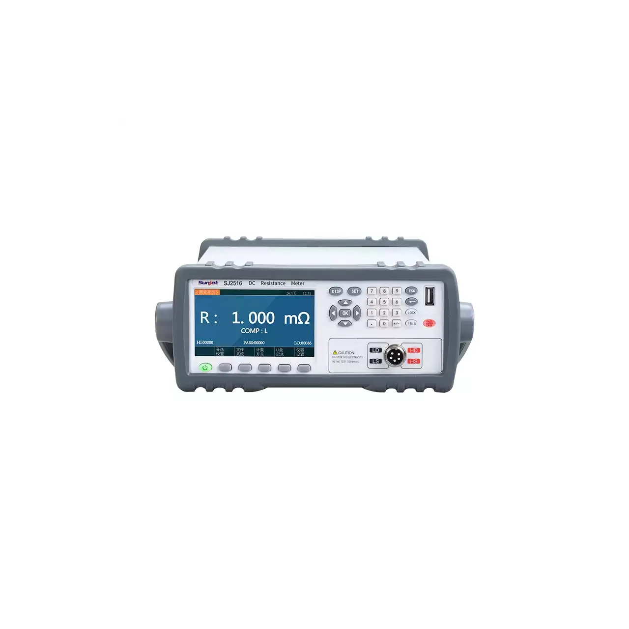
Bench resistance meter seen from the front, with a colour display reading 1.000 mΩ at the left, a numeric keypad at the right and the four test terminals at the lower right

SJ2511 (6 models) · Electrical Test Equipment

Four-Wire DC Low Resistance and Milliohm Meter

Bench four-wire DC resistance meters covering 0.01 µΩ to 2.4 GΩ across the group, with basic accuracy from 0.006% to 0.1%, test current to 10 A and three-level comparator sorting.

Test method
Four-terminal Kelvin, DC test signal
Widest range in the group
0.01 µΩ to 2.4 GΩ
Narrowest range in the group
10 µΩ to 20 kΩ
Basic accuracy
0.006% to 0.1% across the group
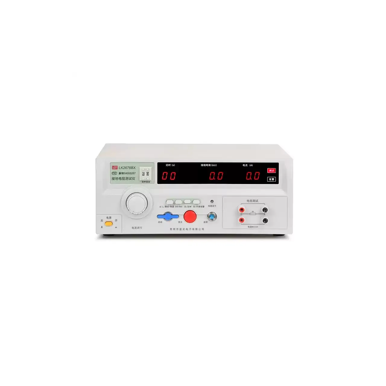
Off-white benchtop tester seen from the front, with a large grey current knob at the left, a black display strip carrying three red digital readouts across the centre, a row of small keys below it and two pairs of red and black terminals on a separate panel at the right

LK2678BX (4 models) · Electrical Safety Testers

Four-Wire Ground Bond Resistance Tester

Four-terminal ground bond tester with 1 to 50 A output across four models, 0 to 600 mΩ ranges, presettable test time and upper limit alarm.

Output current
5 to 32 A on LK2678BX, 10 to 50 A on LK2678, 3 to 32 A on LK7305, 0.01 to 45 A on LK7340
Resistance range
0 to 200 mΩ or 0 to 600 mΩ on LK2678BX and LK2678; 0 to 510 mΩ on LK7305; 0 to 600 mΩ on LK7340
Resistance accuracy
±5% on LK2678BX and LK2678; ±2% on LK7305 and LK7340
Test time
1 to 99 s on LK2678BX, 1 to 999 s on LK2678, 0.1 to 999.9 s on LK7305, 0 or 0.5 to 999.9 s on LK7340
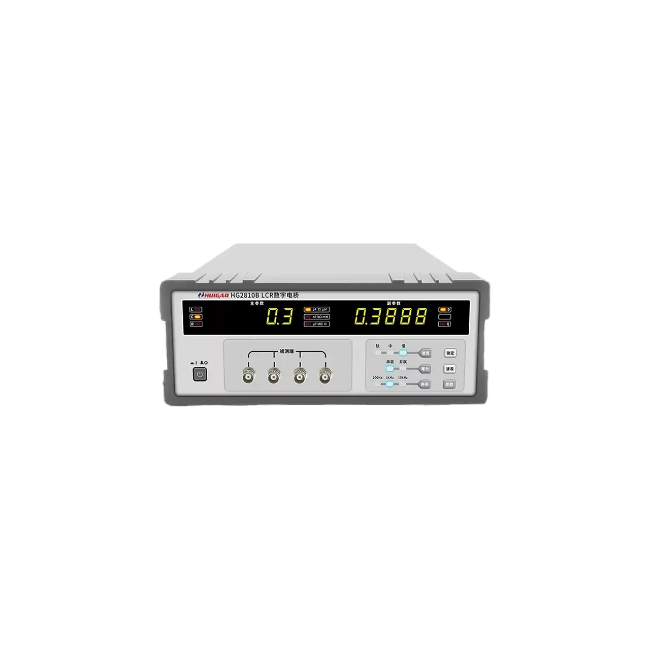
Bench LCR bridge in a grey case, with a five-digit LED display showing a primary and a secondary reading, four coaxial test terminals across the lower centre of the panel, a column of range and function keys at the right and the power switch at the left

HG2810B (6 models) · LCR Meters

Bench LCR Digital Bridge

Bench LCR bridges covering fixed-frequency and wide-band models, with 0.10% or 0.05% basic accuracy, five-terminal connections, bin sorting and optional RS232 and HANDLER interfaces for incoming inspection and production sorting.

Test frequencies
100 Hz, 120 Hz, 1 kHz and 10 kHz on the general models; up to 100 kHz on HG2817 and HG2817B; 8 points to 100 kHz on HG2817D; 37 points from 50 Hz to 200 kHz on HG2817A
Basic accuracy
0.10% on the general models; 0.05% on HG2816A and HG2817A
Test level
0.3 V on HG2810B; 0.1 V, 0.3 V or 1.0 V on most other models; 10 mV to 2.00 V in 10 mV steps on HG2816A and HG2817A
Display ranges
L 0.01 µH to 99999 H and C 0.01 pF to 99999 µF on the general models, with wider ranges on the LCD models

Request a quotation for the SJ5511

Send the configuration you need and we will confirm availability, lead time and terms. Minimum order quantity is 1 pc.

Request for quotation

Request a quotation - SJ5511

Send the technical detail and we will confirm availability, lead time and terms. In-stock items ship within 48 hours; customized specifications typically take 2-10 days. Minimum order quantity is 1 pc.

The more of this you can give us, the fewer exchanges are needed before we can quote.
No file chosen
Datasheet, drawing, BOM or photograph. One file, up to 10 MB (PDF, Office, image or ZIP).

By submitting this form you agree that we may contact you about this enquiry. We do not sell or share enquiry data. See our privacy policy.

Items held in stock are dispatched within 48 hours of order confirmation. Customized specifications are produced to order and typically ship within 2 to 10 days. Transit time then depends on the shipping method and destination.

Request a Quote WhatsApp