- Output voltage
- 5 to 2000 V, continuously settable, ±1%
- Voltage rise rate
- 100 V per second, ±1%
- Voltage measurement accuracy
- 0.5% ±0.1 V
- Leakage range
- 0.00 to 2200.0 µA, error within ±1%
- Constant current accuracy
- 1000 µA ±5 µA and 100.0 µA ±1.0 µA
- Test speed
- 25, 32 or 44 ms per single-parameter reading
- Display
- 240 × 128 dot-matrix LCD, voltage shown as XXXX.X V
- Interface
- HANDLER (PLC) output for a sorting machine
- Body
- 360 × 325 × 105 mm, about 6.8 kg
A gas discharge tube is a gap that is meant to stay open until the moment it is needed. Testing it means finding the voltage at which it closes, and checking that it does not leak before then. Both are high-voltage measurements, and the fixture matters as much as the instrument.
Product overview
The HG2536 is a benchtop tester for ceramic gas discharge tubes and surge arrester parts. It produces a settable output from 5 to 2000 V and measures the voltage across the tube and the current through it, in either constant-voltage or constant-current mode. The sorting result is available on a HANDLER connector at the rear.
The voltage is displayed to one decimal place on the high range, and the leakage range runs to 2200.0 µA. A varistor voltage range and a U1mA reference are also provided, which is what allows the leakage to be measured at a percentage of the breakdown value found on the same part.
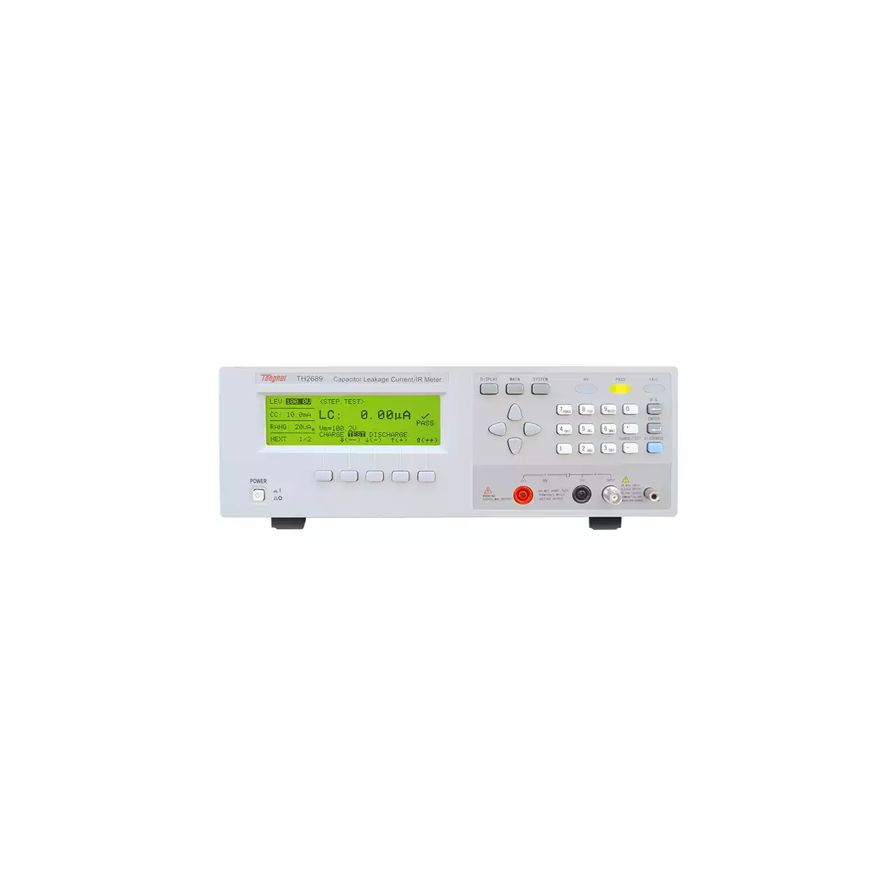
The body is 360 × 325 × 105 mm at about 6.8 kg, with the display at the left of the front panel, the keypad at the right and the two test sockets along the lower edge.
How the gas discharge tube tester works
In constant-voltage mode the instrument applies the set voltage and reads the current. Below breakdown that current is the leakage of an open gap, which is very small; the reading is taken at a defined voltage rather than at whatever the source happens to deliver, which is what makes it comparable between parts.
In constant-current mode the instrument forces a current and reads the voltage. As the current rises the voltage across the tube climbs until the gap breaks down and the voltage collapses, and the point at which that happens is the breakdown voltage. Forcing the current rather than the voltage keeps the energy delivered to the tube bounded, which matters because a gas tube that is driven hard can be damaged by the test itself.
The voltage is raised at a defined rate of 100 V per second. The rate matters: a tube that breaks down at a given voltage when the voltage climbs slowly can break down at a different voltage when it is applied as a step, because the discharge needs time to develop. A stated rise rate is what makes a breakdown figure reproducible.
The test terminals take a four-wire Kelvin lead, so the voltage is sensed at the tube rather than at the instrument output, which keeps the lead and contact resistance out of a measurement taken at up to 2000 V.
How to select the right gas discharge tube tester
The first question is the breakdown voltage of the tube. It has to fall inside the output range with enough headroom to reach it at the stated rise rate, and not so far below the top of the range that resolution suffers. A 2000 V output covers the common surge arrester types; a tube that breaks down above that is outside this instrument.
The second is the leakage specification. The voltage at which leakage is measured, and the current that counts as a failure, both have to be inside the instrument’s range and above its noise. A limit expressed in nanoamps is not checkable on a microamp range.
The third is the test method the specification assumes. Some tube data sheets give a breakdown voltage at a defined rise rate; others give a U1mA value with a leakage limit at a percentage of it. The instrument supports both, and the one to use is the one the drawing states, not the one that is easier to set up.
The fourth is the sorting arrangement. The HANDLER output carries the result, so a line that sorts automatically needs the connector and a fixture that presents the tube repeatably. A bench that tests by hand needs neither.
Send the tube type, the breakdown voltage, the leakage limit and the test method the drawing assumes, and a configuration can be proposed against them.
Measurement limitations and selection considerations
The output is a DC high voltage. The instrument does not produce a surge, so it characterises the DC breakdown and the DC leakage; the impulse response of a gas tube, which is how it behaves in the event it is installed to protect against, is a different measurement and needs a different generator.
Contact quality decides the result at these voltages. A poor contact produces an arc at the terminal before the tube breaks down, and the instrument then reports the arc rather than the tube. This is why the output is settable rather than fixed: running just above the expected breakdown keeps the test energy low and the contact clean.
The tube’s history matters. A gas tube that has been struck repeatedly can break down at a lower voltage than a new one, and a tube measured immediately after a breakdown may need time to de-ionise before the next reading is meaningful. A fixture that tests the same tube twice in quick succession will not give the same two numbers.
The leakage of an open gap is small and the measurement is at high voltage, so cable movement and humidity both show up in the reading. A dry day and a humid one are not the same test.
Finally, the material gives a percentage-of-U1mA leakage condition without stating the default percentage or its range, and describes the sorting output without a bin count. Those are worth settling before the instrument is written into a test procedure.
Every value below is taken from source documentation. Where a parameter is not stated in the available material it is marked as information required rather than estimated.