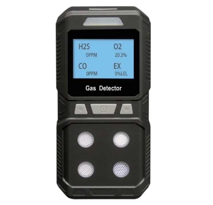
A fixed gas detector answers a different question from the instruments usually compared with it. A portable detector asks whether the atmosphere is safe for a person who is about to enter it. A fixed detector asks whether anything has changed since the last time someone looked, at a point where a gas would collect if it escaped, and it is expected to still be answering that question months later without attention.
That difference drives the whole specification. Because the instrument sits in the atmosphere it monitors continuously rather than briefly, where it is placed and how it survives become part of the engineering rather than accessories to it.
What the installation consists of
The detector is one device. Around it the material describes three arrangements, and the choice between them is a wiring decision rather than a measurement decision. In the stand-alone form the detector is supplied alone and plugged in, with the audible and visual alarm raised at the point and no wiring between units. In the wired form the detector and a controller are linked by four-core cable, which the customer provides, and one controller can serve several detectors. In the wireless form the two are linked without any wiring at all, with the controller run from 220 V and the detector supplied with a power adaptor that matches automatically once the detector is energised.
The controller is what turns readings into actions. It takes up to 99 detectors, annunciates alarms audibly and visibly, provides two relay outputs and holds 999 alarm events through a power failure. Its optional RS-485 interface speaks standard Modbus/RTU, which is the route to a PLC, a DCS, a GDS or a fire panel, and its relay contacts are what start a fan, close a valve or switch an alarm lamp.
How the detection works
The combustible channel burns a small amount of the gas on a heated catalytic element and measures the heat released, which reads directly as a fraction of the lower explosive limit. It needs oxygen to work and is permanently poisoned by silicones, leaded compounds and some solvents. The oxygen, hydrogen sulphide and carbon monoxide channels use electrochemical cells, each reacting its gas at an electrode and producing a current proportional to concentration; a cell is consumed by the gas it measures, so its life follows exposure rather than the calendar.
The material gives the recovery time, ≤10 s, rather than the response time. The two are not the same figure: one describes how quickly the reading falls back after the gas has gone, which is what makes the detector usable again after an excursion, and the other describes how quickly it rises when the gas arrives. On a fixed installation both matter, and only one is stated.
Siting the detector
Where the detector is mounted decides whether it works at all, and it is decided before any instrument is chosen. A gas lighter than air rises and collects at the highest point of the space, so a detector for it belongs high. A gas heavier than air settles, which means it will be found first in pits, sumps, trenches and at floor level. A detector placed at breathing height for a heavy gas reads air, reports it as safe, passes its calibration and is in the wrong place - a failure that is harder to spot than an instrument that is plainly not working.
The housing is built for that duty. It is flameproof die-cast aluminium with a sealing ring at every joint and an IP66 rating, because the detector is installed inside the classified area rather than protected from it. Its own certification therefore forms part of the installation: the flameproof construction, the gas group it is valid for and the temperature class it is allowed to reach all have to match the area. The two temperature windows in the material - -40 to 70 °C for the combustible channel and -20 to 50 °C for the toxic channels - follow from the sensor technologies rather than from the housing, and they mean a mixed installation has to be checked channel by channel against the place it is going into.
The controller and what it can drive
The controller is where a detection point becomes part of a plant. Two relay outputs are available as standard, and what they operate decides how many are needed: an alarm that only has to be noticed is different from a contact that has to start ventilation or close a valve while the event is still happening. The material lists fans, solenoid valves, alarm lamps and a cloud platform among the possible interlock and monitoring options, with the optional host software offering record query, curve analysis, device monitoring and a large-screen display.
Two practical points belong with that. The first is that the lower limit of the controller’s operating temperature is quoted as 20 °C in the material, which its own note suggests may be a misreading of 0 °C, so the cabinet it lives in should be checked against the conservative reading until that is confirmed. The second is that the controller’s menu is in Chinese, which the material states plainly; whether an English menu is available is a question for the enquiry rather than an assumption.
Measurement limitations and selection considerations
The most important gap on this page is that the material does not state the measuring range, the resolution or the alarm setpoints of the detector. For a gas detector those are the first figures normally compared, and they are listed as information required rather than filled in from a similar instrument. The controller’s own T90 < 30 s figure is its transmission and annunciation time, not the detector’s response time, and should not be read as one.
Three further points are worth stating. The material gives two sets of dimensions for the detector - 186 × 142 × 69 mm in the parameter table and 239 × 178 × 90 mm in the outline drawing - and keeps both; since the drawing is what a mounting bracket is made from, the discrepancy should be settled before installation. The humidity limits differ between the two devices, at 0-95 %RH for the detector and ≤93 %RH for the controller, so a system sharing one room should be assessed against the stricter figure. And the wireless form’s power arrangement is described in the material as containing a text misalignment, so the relationship between the detector’s battery and the adaptor it comes with has to be confirmed rather than inferred.
Ordering
The items that fix the answer are the gas or gases at the point, where the point is and at what height, the classification of the area including the gas group and temperature class, the number of points and how far apart they are, whether a cable route exists or the link has to be wireless, what each relay output has to operate and whether that action is automatic, and which certificates the installation has to be signed off against. A plan with the points marked and a gas list is enough to issue a covering quotation, which can then be refined as the siting is agreed. Quantity, destination port and required delivery date complete the enquiry.
Every value below is taken from source documentation. Where a parameter is not stated in the available material it is marked as information required rather than estimated.