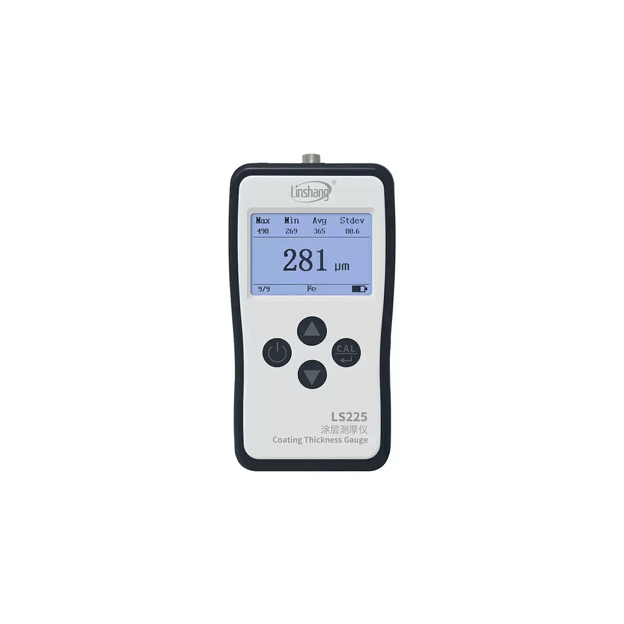
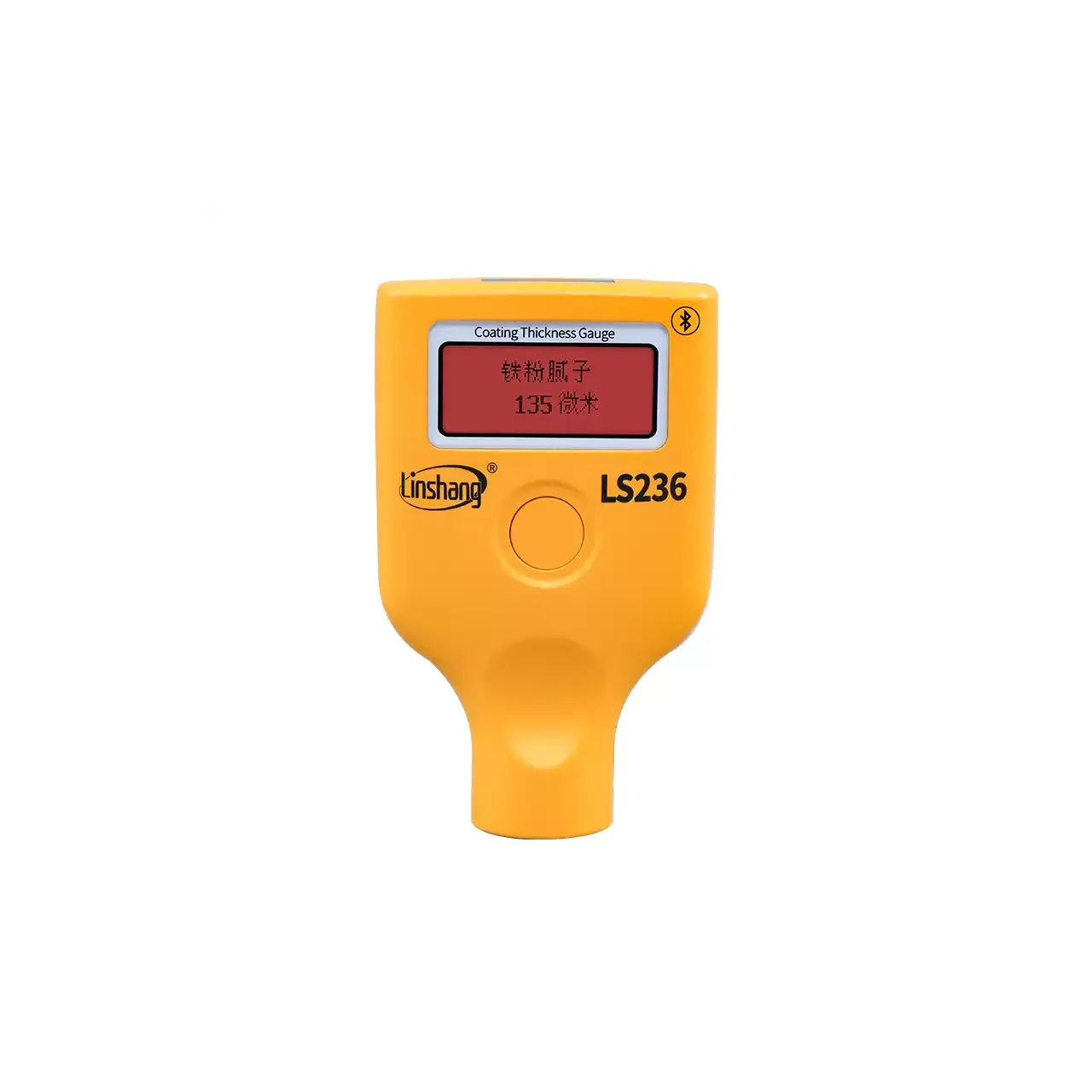
What a coating thickness gauge is
A coating thickness gauge measures the depth of a layer sitting above a substrate, without cutting through it. Paint on steel, zinc on steel, anodising on aluminium, copper on a board and a plastic film on a metal sheet are all the same measurement problem: a non-magnetic or non-conductive layer, a solid substrate beneath it, and a figure that has to be shown to be inside a tolerance. It is one of the few coating checks that is non-destructive, which is why it is taken on the delivered part and not only on a coupon.
The method is decided by the substrate, not by the coating. A magnetic induction probe works on ferromagnetic steel and iron and reads how far the coating pushes the probe away from the substrate; an eddy current probe works on non-ferrous metals such as aluminium, copper and austenitic stainless steel and reads the effect the coating has on an induced field. A gauge that carries both can switch between them and identify the probe in use, but the reading is always a reading for one method, and the two are not interchangeable on the same substrate.
What limits the measurement is mostly geometry. Curvature, the proximity of an edge, and a substrate thinner than the method needs all distort the field and bias the reading, and each has a published limit attached to the probe. Above those limits the error grows quietly, so the practical task is to match the probe range to the expected thickness and then to check that the part satisfies the probe conditions before trusting the number.
How a coating thickness gauge measures
A magnetic induction gauge energises a coil in the probe and measures the reluctance of the path between the probe and the ferromagnetic substrate. The coating is a gap in that path, so the reading is essentially a distance measurement across the layer, which is why the method depends on the substrate being genuinely ferromagnetic and on the coating being genuinely non-magnetic. Nickel plating and some stainless steels break that assumption, and the gauge reads them as substrate rather than as coating.
An eddy current gauge drives an alternating field into a conductive substrate and measures the change in impedance caused by eddy currents flowing in it. Because the field is affected by the standoff, the same coil geometry becomes a thickness reading when the substrate is known. It is the method for aluminium, copper, brass and 300-series stainless steel, where a magnetic gauge would read nothing useful at all.
Both methods are relative measurements and are calibrated rather than absolute. Zeroing on the bare substrate establishes the datum, and one or two foils of known thickness establish the slope, with the two-point form correcting the gain as well as the offset. Almost every surprising reading traces back to that setup: zeroing on a coated area, using a foil outside the probe range, or leaving the calibration untouched when the probe is changed. The physical conditions - curvature, edge distance, substrate thickness, temperature - are the second half of the same story, and the instrument cannot correct for them on its own.
Configuration choices
Most of the specification is fixed by these decisions rather than by the accuracy class. Each one constrains the next, which is why they are settled in order.
| Configuration | Options to fix | What it actually decides |
| Measuring method | Magnetic induction, eddy current, or a gauge carrying both and identifying the probe automatically | Whether the intended substrate can be measured at all. The method follows the substrate material, not the coating. |
| Probe range | A short-range probe for thin coatings, a long-range probe for thick ones, and the resolution each offers | The thickness band that can be read with useful resolution. A probe stretched to the end of its range loses both accuracy and repeatability. |
| Probe format | A probe built into the housing, or a separate probe on a cable | Whether the instrument can reach the surface. An integral probe cannot be laid flat on a curved or recessed area. |
| Probe geometry | The tip form and the minimum measurement area the probe needs | Whether small parts, narrow areas near an edge, or tight curvature can be measured without a correction that the instrument does not know about. |
| Calibration method | One-point zeroing, two-point calibration against foils, or the factory setting left untouched | How much of the reading error is removed. Zeroing alone corrects the offset and leaves the gain uncorrected. |
| Data handling | Direct display, internal memory with statistics, and export to a host or a printer | Whether a batch record with mean, minimum, maximum and standard deviation can be produced, which acceptance criteria increasingly require. |
| Limits and alarms | Settable upper and lower limits with an audible or visual indication | Whether the instrument can be used for screening by an operator who is not reading the numbers, and what tolerance the limits can express. |
| Verification | Reference foils, reference substrates of known thickness, and the interval at which they are used | Whether the gauge can be shown to be reading correctly on the day, which is what a quality record has to demonstrate. |
How to choose a coating thickness gauge
| Factor | Why it decides the answer | How to settle it before enquiring |
|---|
| The substrate material | It selects the method, and a magnetic gauge reads nothing useful on aluminium while an eddy current gauge reads nothing useful on carbon steel | State the substrate exactly, including the grade, because some stainless steels and nickel layers behave as the opposite of what their name suggests. |
| The expected coating thickness and its tolerance | The probe range and its resolution have to bracket the tolerance, not merely the nominal figure | Give the target thickness and the tolerance band, and the process that produces it. |
| Whether the coating may be magnetic | Nickel and some alloy coatings defeat a magnetic induction gauge by acting as part of the substrate | State the coating material and its deposition method, not only its name. |
| The geometry of the part | Curvature, edges and small areas all bias the field, and each probe has published limits beyond which the reading is not valid | Give the smallest radius, the distance from the nearest edge, and the smallest area to be measured. |
| Substrate thickness | Below a critical thickness the substrate stops behaving as an infinite body and the reading falls | Give the substrate thickness, and whether the part is a sheet or a heavy section. |
| Whether results must be recorded | A batch record with statistics changes the instrument class, and often the way the readings are taken | State the acceptance criteria, how many readings per part, and in what form the record is required. |
If any of these are still open, send what is known. A quotation can be issued against a described part and refined once the gaps are filled.
The nearest alternatives
These are the types an enquiry for a coating thickness gauge usually turns out to be, and the point at which the choice is genuinely decided.
| Nearest alternative | What separates it from a coating thickness gauge |
| Surface roughness testers | Measures the texture of the outermost surface rather than the depth of the layer beneath it. A coated part often carries both requirements, and the two are measured separately because a smooth coating can still be too thin and a thick one can still be rough. |
| Hardness testers | Measures resistance to indentation in the material, which for a coated part is usually a question about the substrate rather than about the layer. It presses into the surface, so it is not a substitute where the coating must remain intact. |
| Ultrasonic thickness gauges | Measures the thickness of the material itself, and can be set to resolve a coating as one of two echoes on some instruments. That is a wall-thickness instrument answering a remaining-life question; a coating gauge answers a finish and corrosion-protection question. |
| Magnetic particle testing equipment | Also uses a magnetic field on ferromagnetic parts, but looks for cracks rather than for layer depth. Sharing a physical principle is not the same as sharing a purpose, and neither instrument reports what the other does. |
| Eddy current flaw detectors | Use the same induced-field principle to find discontinuities in conductive material rather than to measure a layer above it. Some instruments combine both functions, and where they do, the two modes are calibrated separately. |
| Destructive coating examination | A microscope measurement of a cut section, or a chemical strip-and-weigh. Slower and it consumes the sample, but it is the reference method where a dispute arises, and it is worth keeping a coupon for exactly that reason. |
Roughness, hardness and coating thickness are the three surface requirements a drawing most often names together; a coating gauge answers only the last of them, and the three are measured with three different instruments.
What to include in the enquiry
The first reply can be a quotation rather than a set of questions if the enquiry carries these. Where a figure is not known, send the duty description and we will confirm what it implies.
- The substrate material and grade, and its thickness
- The coating material and how it is applied
- The expected coating thickness, with its tolerance band
- The geometry of the part, including the smallest radius, the nearest edge and the smallest measurement area
- Whether the coating may be magnetic, and whether any nickel or alloy layer is present
- Whether the coating is on one side or both, and whether the reverse face is accessible
- Whether readings must be stored and exported, and in what form the record is required
- The acceptance criteria and the number of readings per part
- Reference foils or reference substrates available locally for verification
- Quantity, destination port and required delivery date