Industrial Testing Equipment · Coating Thickness Gauges

High-Precision Coating Thickness Gauge

Coating thickness gauge with interchangeable magnetic and eddy current probes, five-point calibration and an accuracy of ±(2% of reading + 0.3 µm) for plating and paint on small parts.

LS225 (4 models) ·

Key specifications

Measuring range
0.0 to 500 µm with F500; 0.0 to 1500 µm with N1500; 0.0 to 2000 µm with N2000
Accuracy
±(2% H + 0.3 µm) after five-point calibration, H being the standard value
Repeatability
≤ (0.8% H + 0.1 µm) on F500 and N1500 with the hand press stand; ≤ ±(1% H + 0.2 µm) on N2000
Probes
F500 magnetic induction; N1500 and N2000 eddy current
Minimum substrate thickness
0.1 mm on a ferromagnetic substrate; 0.03 mm on a non-ferrous substrate
Minimum measuring area
7 mm
Display
240 × 160 dot matrix LCD with Max, Min, Avg and Stdev of the last nine readings
Calibration
Zero point plus one to five calibration points
Body
148 × 76 × 26 mm, four AAA alkaline cells
Probe size
F500 and N1500 110 mm long by 15 mm diameter; N2000 95.5 mm long by 30 mm diameter

A coating that is only a few micrometres thick is where a general-purpose gauge stops being useful. The reading is small, the tolerance is tighter than the reading, and the difference between one operator and the next becomes visible in the numbers. This instrument is aimed at that end of the work.

Product overview

One body, three probes, five ways of buying it. The body carries the display, the calibration and the statistics; the probe carries the coil and sets which method is applied and over what range.

The probes are deliberately small. Two of them are the size of a thick pen and read an area not much wider than a screw head, which is what makes a bolt, a bracket or a stamped contact readable at all. The third is wider and is aimed at painted board material and thicker coatings.

The body is held in one hand and the probe in the other, on a cable. A hand press stand can replace the hand for the two thin-coating probes, and that is the configuration the tighter repeatability figures belong to.

How the instrument measures a thin coating

Both methods measure a gap. Over a ferromagnetic substrate, the probe drives a magnetic circuit through the coating and measures how much the gap weakens it. Over a conductive non-ferrous substrate, the probe drives an alternating field and measures the eddy currents induced in the metal beneath, which change with the distance to the probe.

Neither method measures the coating directly. Both measure the effect of distance on a field, which is why the substrate has to be known before the number means anything, and why the instrument shows which substrate it believes it is on.

What makes a thin coating readable is the stability of that signal, not the size of the display. The probe digitises close to the coil, the instrument compensates for temperature, and the calibration corrects the offset on the bare part and the gain against foils of known thickness. The accuracy figure is quoted after a five-point calibration because that is the condition under which the linearity has been corrected; a one-point calibration leaves the far end of the range uncorrected.

The statistics on the screen are part of the measurement rather than a convenience. Taking several readings on one part and reading the spread tells the inspector whether the surface or the technique is the source of the variation.

How to select the right probe

The substrate decides the method, and the method decides the probe. Iron and ferromagnetic alloys take the magnetic probe; copper, aluminium, brass, magnesium and zinc take one of the eddy current probes.

The coating decides nothing about the method and everything about the range. A thin zinc or paint layer on steel sits inside the magnetic probe’s range with resolution to spare; a thick coating on aluminium needs the longer eddy current range.

The size of the part decides the probe more often than the range does. Where the measuring spot has to fit between a thread and a shoulder, the narrow probes are the only ones that will sit flat. Where the part is board material or a broad panel, the wider probe is easier to keep square.

The stand is a decision about the acceptance limit. If the tolerance is wide compared with the reading, hand pressure is good enough. If the tolerance is tight, the stand removes a variable the operator cannot feel.

Measurement limitations and selection considerations

A coating over a substrate thinner than the probe expects is not measurable, whatever the display says. Below the stated minimum substrate thickness the field passes through the part and into whatever is behind it, and the reading becomes a property of the bench rather than of the part. Thin sheet, foil and small machined parts are where this bites.

Edge and curvature effects are the second limit. Near an edge or on a tight radius the field has less material around it, and the reading drifts low rather than failing. The minimum area and radius are conditions of validity, not targets.

The method cannot separate layers. Primer, topcoat and clear coat on the same panel are read as one film, and a plated layer under paint is invisible to the reading. Where the individual layer thickness is the acceptance criterion, a cross-section is the only answer.

Finally, the probe is a precision part with a wear surface. A dropped or dragged probe drifts, and the drift appears as a slow change in the readings rather than as a fault. Checking against a known foil at the start of a shift is cheaper than discovering it at the end of one.

Features

  • A stated accuracy of ±(2% of reading + 0.3 µm), which is what makes a 1 to 10 µm plating readable rather than a rounding of the display
  • Digital probe signal processing with temperature compensation, so a reading taken after the instrument has warmed up or cooled down does not drift away from the calibration
  • Three interchangeable probes covering magnetic and eddy current work over three ranges, so one body serves plating, paint and anodising
  • A measuring area of 7 mm, small enough for screws, bolts and formed parts that a full-size probe cannot sit on
  • A hand press stand for the F500 and N1500 probes, which holds the probe square and applies the same load each time
  • Statistics of the last nine readings shown together with the current value, so a spot check can be judged without writing numbers down
  • Zero plus one to five calibration points, which lets the linearity be corrected against the workshop’s own reference foils
  • The N2000 probe triggers under its own weight, removing the difference between one operator’s press and another’s
  • Language, unit, power-off delay and measuring mode set on the instrument, including an English interface

Technical specifications

Every value below is taken from source documentation. Where a parameter is not stated in the available material it is marked as information required rather than estimated.
Measurement
PrincipleMagnetic induction on ferromagnetic substrates; eddy current on non-ferrous substrates; set by the probe fittedStandard
Measuring rangeF500 0.0 to 500 µm; N1500 0.0 to 1500 µm; N2000 0.0 to 2000 µmStandard
ResolutionF500 0.1 µm to 99.9 µm and 1 µm above; N1500 and N2000 0.1 µm to 99.9 µm, 1 µm to 999 µm and 0.01 mm above 1.00 mmStandard
Accuracy±(2% H + 0.3 µm) after five-point calibration, H being the standard valueStandard
RepeatabilityF500 and N1500 ≤ (0.8% H + 0.1 µm) on the hand press stand; N2000 ≤ ±(1% H + 0.2 µm)Standard
Unitsµm and milStandard
Measuring intervalF500 1.5 s single and 0.4 s continuous; N1500 and N2000 0.8 s single and 0.4 s continuousStandard
Minimum radius of curvature1.5 mm convex and 10 mm concave, all three probesStandard
Minimum substrate thicknessF500 0.1 mm; N1500 and N2000 0.03 mmStandard
Minimum measuring area7 mmStandard
Substrate indicationFe for a ferromagnetic substrate, NFe for a non-ferrous oneStandard
Probes
F500Magnetic induction, for coatings on iron and ferromagnetic metals, including zinc and copper plating on steelStandard
N1500Eddy current, for coatings on non-ferromagnetic metals such as copper, aluminium, brass, magnesium and zincStandard
N2000Eddy current, for paint and anodising on non-ferromagnetic metals and for coatings on PCB material; triggered by the weight of the probeStandard
Probe dimensionsF500 and N1500 110 mm long by 15 mm diameter; N2000 95.5 mm long by 30 mm diameter, cable excludedStandard
Hand press standOptional with the F500 and N1500 sets; it holds the probe square and applies a repeatable loadOptional
Display and calibration
Screen240 × 160 dot matrix LCDStandard
StatisticsMaximum, minimum, average and standard deviation of the most recent nine readingsStandard
CalibrationZero point, one to five points, restore the previous calibration, restore the factory calibration, view the current calibrationStandard
SettingsLanguage Chinese or English; unit µm or mil; automatic power-off from 1 to 9 minutes; single or continuous measuring modeStandard
Power and environment
SupplyFour 1.5 V AAA alkaline cellsStandard
Body dimensions148 × 76 × 26 mmStandard
Operating temperature0 to 50 °CStandard
Storage temperature−20 to 60 °CStandard
Packing case290 × 340 × 90 mmStandard

Available models

Selection table
Model Configuration Key ranges Availability
LS225 + F500 Body with the F500 magnetic induction probe 0.0 to 500 µm; 0.1 mm minimum ferrous substrate; 7 mm area The set for paint, powder and plating on steel
LS225 + N1500 Body with the N1500 eddy current probe 0.0 to 1500 µm; 0.03 mm minimum non-ferrous substrate; 7 mm area The set for coatings on aluminium, copper, brass and zinc
LS225 + N2000 Body with the N2000 eddy current probe 0.0 to 2000 µm; 0.03 mm minimum non-ferrous substrate; 30 mm probe diameter The set for paint on PCB material and thicker coatings on non-ferrous parts
LS225 + F500 + stand F500 set with the hand press stand 0.0 to 500 µm; repeatability quoted on the stand For thin plating, where the press load matters to the reading
LS225 + N1500 + stand N1500 set with the hand press stand 0.0 to 1500 µm; repeatability quoted on the stand For thin coatings on non-ferrous parts, measured at a fixed load

Certification and compliance

Certification documents not yet supplied

Certifications are only published once a certificate copy can be produced, so this section is deliberately empty rather than populated with assumed approvals. Tell us which approvals your application requires and we will confirm what is available for this instrument.

Parameters still to be confirmed

The following are required for a complete specification but are not stated in the documentation supplied to us. They are listed rather than estimated:

  • The conformity standards the instrument is built to, such as the relevant ISO or ASTM numbers, which the material does not state
  • Ingress protection rating
  • Whether a calibration certificate is supplied and whether the reference foils are traceable
  • Warranty period and its terms
  • Runtime on the four AAA cells, which the material does not give
  • The probe cable length, which is excluded from the quoted probe dimensions
  • Whether the hand press stand can be bought separately for an instrument already in service
  • The resolution of the statistics display, which the material does not state
  • The exact derivation of the repeatability figure advertised as 0.1 µm, which the parameter table states as a percentage of reading plus an offset
  • Whether an English-language datasheet and operating manual are available

Frequently asked questions

Which probe reads zinc plating on a steel part?

F500. The coating is metallic but non-magnetic, and the substrate is ferromagnetic, so the magnetic induction method sees the zinc as a gap in the magnetic circuit. The same probe covers paint and powder on steel. Zinc over aluminium is a different case: there the substrate is non-ferromagnetic, and the eddy current probe is the one that applies.

Why does the stand change the repeatability figure?

Because it removes the operator. A probe pressed by hand is never exactly square to the surface and never at exactly the same load, and on a coating only a few micrometres thick that variation is a large part of the reading. The hand press stand holds the probe perpendicular and applies a consistent load, which is the condition under which the tighter repeatability figure is quoted.

Is five-point calibration necessary for every batch?

Not for every batch, but it is what the accuracy figure belongs to. Zeroing on an uncoated part removes the offset; one or two points correct the gain near the thickness in use; five points correct the linearity across the range. Where the acceptance limit is close to the reading, calibrate at the thickness being judged, on the substrate the parts are made from.

What is needed before a quotation?

The substrate material and its thickness, since a thin substrate decides whether the probe can read at all; the coating material and how it is applied; the thickness band and tolerance to be judged; the smallest area available on the part; and whether the work is a laboratory check or a line inspection, which decides on the stand. Quantity and destination complete the enquiry.

Related products

Other models in the same range

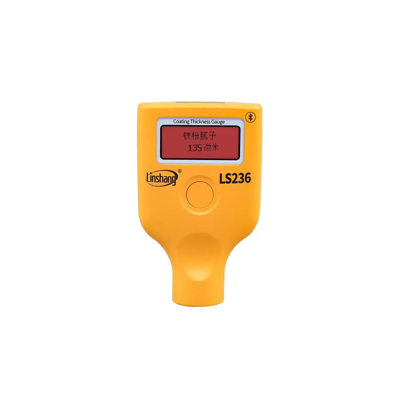
Yellow handheld coating thickness gauge with a red backlit display in a dark bezel, a single round key below the screen and a narrow probe barrel at the lower end

LS238 (5 models) · Coating Thickness Gauges

Handheld Automotive Paint Thickness Gauge

Handheld paint thickness gauge with a 3500 µm range, automatic recognition of steel, galvanised steel, aluminium and plastic substrates, and a putty detection warning for used-car inspection.

Measuring range
0.0 to 3500 µm
Resolution
0.1 µm from 0 to 99.9 µm; 1 µm from 100 to 3500 µm
Accuracy
≤ ±(3% H + 2 µm), where H is the standard value
Substrates
Ferrous by Hall effect; non-ferrous by eddy current; identified automatically
Split-probe coating thickness gauge in a black housing with a cable entering the top, a backlit display reading 49.4 um above a line showing the probe type and single measurement mode, and a twelve-key control pad below with eight keys grouped in coloured pairs and a round key in the centre

TT220 (3 models) · Coating Thickness Gauges

Dual-Principle Coating Thickness Gauge

Magnetic and eddy current coating thickness gauge measuring 0 to 1250 µm on steel and aluminium, with automatic probe identification, statistics, limit alarms and 500 stored readings.

Model
TT220 / TT230 / TT260 and the split-probe F and N series
Measuring principle
Magnetic induction on ferromagnetic substrates, eddy current on non-ferrous substrates, selected automatically by the probe fitted
Measuring range
0 to 1250 µm with the standard F1 or N1 probe; 0 to 400 µm with F400; 0 to 5000 µm with F5; 0 to 10000 µm with F10; 0 to 2000 µm on the integral TT220
Resolution
0.1 µm below 100 µm; 10 µm on the long-range F10 probe; 1 µm above 100 µm on the integral model

Request a quotation for the LS225

Send the configuration you need and we will confirm availability, lead time and terms. Minimum order quantity is 1 pc.

Request for quotation

Request a quotation - LS225

Send the technical detail and we will confirm availability, lead time and terms. In-stock items ship within 48 hours; customized specifications typically take 2-10 days. Minimum order quantity is 1 pc.

The more of this you can give us, the fewer exchanges are needed before we can quote.
No file chosen
Datasheet, drawing, BOM or photograph. One file, up to 10 MB (PDF, Office, image or ZIP).

By submitting this form you agree that we may contact you about this enquiry. We do not sell or share enquiry data. See our privacy policy.

Items held in stock are dispatched within 48 hours of order confirmation. Customized specifications are produced to order and typically ship within 2 to 10 days. Transit time then depends on the shipping method and destination.

Request a Quote WhatsApp